Chapter 1: Introduction
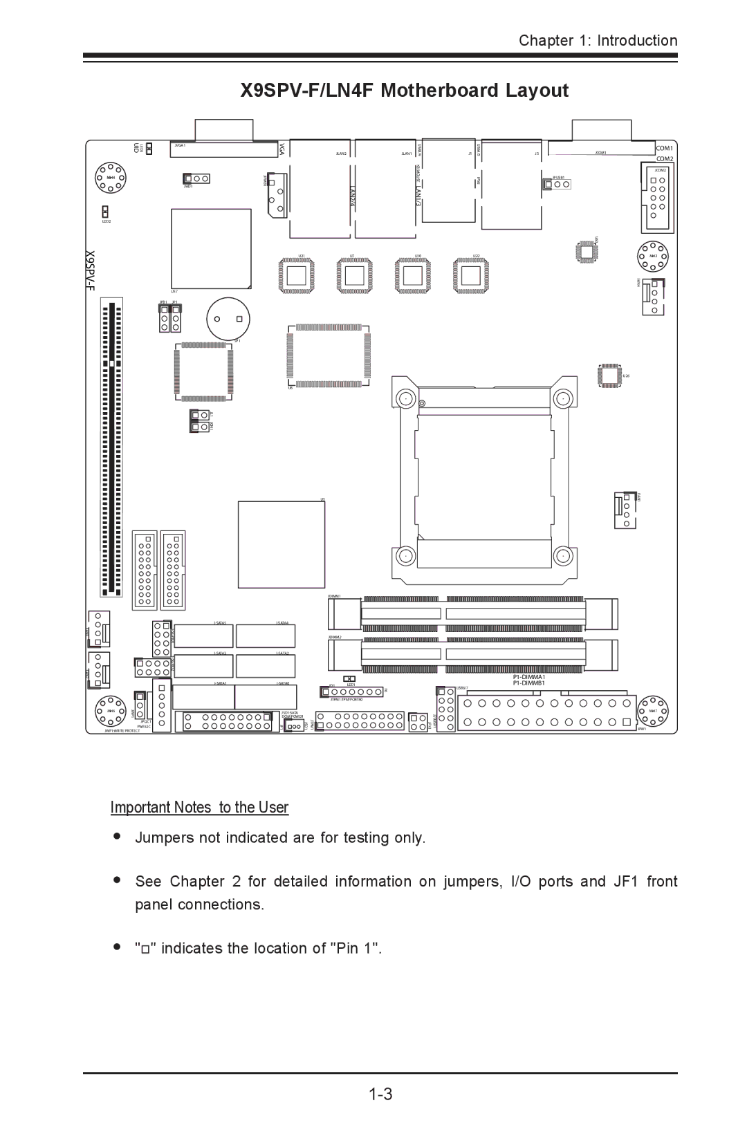
X9SPV-F/LN4F Motherboard Layout
UID | LED3 | JVGA1 | VGA | JLAN2 |
|
|
|
| |
MH4 |
| 1 | JIPMB1 | LAN2/4 |
|
| JWD1 |
|
|
JLAN1 | USB8/9 | J1 | USB4/5 |
|
| KB/MOUSE |
| IPMI |
|
|
|
| ||
| LAN1/3 |
|
|
|
|
|
|
|
J3
JCOM1
JPUSB1
COM1
COM2
JCOM2
LED2
X9SPV-F U57
JPB1 JP1
SP1
![]() 1 JL JOH1
1 JL JOH1
U21U7
U6
U3
U10 |
| U22 |
|
|
|
|
|
|
0 U6
FAN4
U26
![]()
![]()
![]() FAN1
FAN1
MH2
|
| |
FAN3 |
| |
|
| |
FAN2 |
| |
|
| |
| MH6 | JWP1 |
|
| |
|
| JPI2C1 |
|
| PWR I2C |
| JWP1:WRITE PROTECT | |
| JDIMM1 |
|
|
| |
| JDIMM2 |
|
|
| |
JD1 | LED1 | |
| JTPM1:TPM/PORT80 | |
JSD1:SATA |
|
|
DOM POWER | PMJT 1 JSD1 |
|
JF1 |
| |
F6 | USB6/7 |
| |
| 1 |
| J20USB JPK1 |
MH7
JPW1
Important Notes to the User
•Jumpers not indicated are for testing only.
•See Chapter 2 for detailed information on jumpers, I/O ports and JF1 front panel connections.
•"![]() " indicates the location of "Pin 1".
" indicates the location of "Pin 1".