![]()
![]()
![]()
![]()
![]()
![]() X9SPV Motherboard Series User's Manual
X9SPV Motherboard Series User's Manual
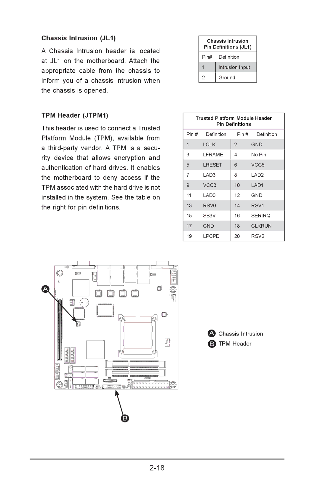
Chassis Intrusion (JL1)
A Chassis Intrusion header is located at JL1 on the motherboard. Attach the appropriate cable from the chassis to inform you of a chassis intrusion when the chassis is opened.
TPM Header (JTPM1)
This header is used to connect a Trusted Platform Module (TPM), available from
a
TPM associated with the hard drive is not installed in the system. See the table on the right for pin definitions.
Chassis Intrusion
Pin Definitions (JL1)
Pin# Definition
1Intrusion Input
2Ground
Trusted Platform Module Header
Pin Definitions
Pin # | Definition | Pin # | Definition |
1 | LCLK |
| GND |
2 | |||
3 | LFRAME |
| No Pin |
4 | |||
5 | LRESET |
| VCC5 |
6 | |||
7 | LAD3 |
| LAD2 |
8 | |||
9 | VCC3 |
| LAD1 |
10 | |||
11 | LAD0 | 12 | GND |
13 | RSV0 | 14 | RSV1 |
15 | SB3V | 16 | SERIRQ |
17 | GND | 18 | CLKRUN |
19 | LPCPD | 20 | RSV2 |
|
|
|
|
UID
JVGA1
VGA
COM1
MH4
JLAN2JLAN1
LAN2/4 | LAN1/3 |
J1
J3
JCOM1
JPUSB1
COM2
JCOM2
LED2
A
X9SPV-F
MH6
JPI2C1
PWR I2C
JWP1:WRITE PROTECT
U57 JPB1 JP1
| U21 |
| U7 | U10 | U22 |
| SP1 |
|
|
|
|
| U6 |
|
|
|
|
|
| U3 |
|
|
|
|
| JDIMM1 |
|
|
|
|
|
|
| ||
|
| JDIMM2 |
|
|
|
|
|
|
| ||
|
|
|
|
| |
JD1 | LED1 |
| |||
|
|
|
| F6 | USB6/7 |
|
| JTPM1:TPM/PORT80 |
|
| |
| JSD1:SATA |
|
|
|
|
| DOM POWER |
|
|
|
|
MH2
U26
AChassis Intrusion
B TPM Header
MH7
JPW1
B