![]()
![]()
![]()
![]()
![]()
![]() X9SPV Motherboard Series User's Manual
X9SPV Motherboard Series User's Manual
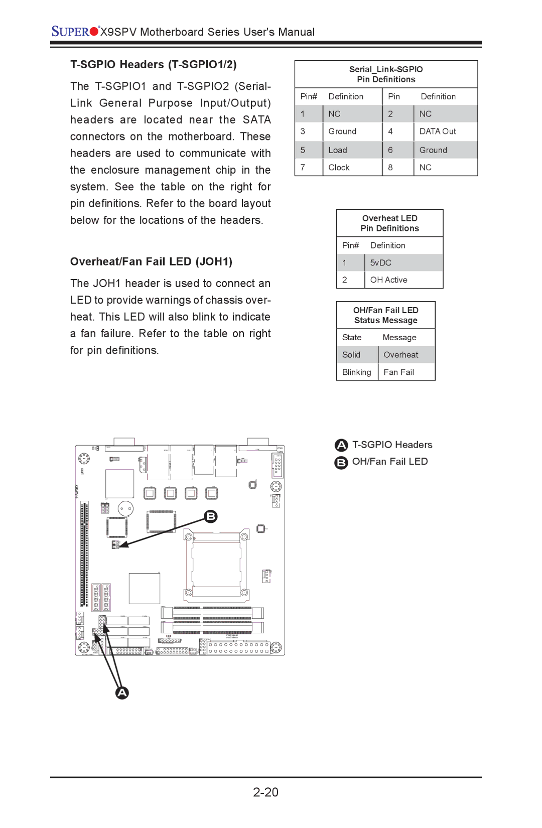
T-SGPIO Headers (T-SGPIO1/2)
The
Pin Definitions
Link General Purpose Input/Output) headers are located near the SATA connectors on the motherboard. These headers are used to communicate with the enclosure management chip in the system. See the table on the right for pin definitions. Refer to the board layout
Pin#
1
3
5
7
Definition
NC
Ground
Load
Clock
Pin 2 4 6 8
Definition
NC
DATA Out
Ground
NC
below for the locations of the headers.
Overheat/Fan Fail LED (JOH1)
The JOH1 header is used to connect an LED to provide warnings of chassis over- heat. This LED will also blink to indicate a fan failure. Refer to the table on right for pin definitions.
Overheat LED
Pin Definitions
Pin# Definition
15vDC
2OH Active
OH/Fan Fail LED
Status Message
State |
| Message |
Solid |
| Overheat |
| ||
Blinking |
| Fan Fail |
| ||
|
|
|
UID | JVGA1 |
MH4 |
|
LED2 |
|
| U57 |
JPB1 | JP1 |
VGA | JLAN2 | JLAN1 | J1 | J3 | JCOM1 | COM1 |
|
|
|
|
|
| COM2 |
|
|
|
|
|
| JCOM2 |
|
|
|
|
| JPUSB1 |
|
| LAN2/4 | LAN1/3 |
|
|
|
|
U21 | U7 | U10 | U22 |
|
| MH2 |
AT-SGPIO Headers
BOH/Fan Fail LED
MH6 |
JPI2C1 |
PWR I2C |
JWP1:WRITE PROTECT |
SP1
U6 |
|
|
| U3 |
|
| JDIMM1 |
|
|
| |
| JDIMM2 |
|
|
| |
JD1 | LED1 | |
|
| F6 |
| JTPM1:TPM/PORT80 | |
JSD1:SATA |
|
|
DOM POWER |
|
|
B
U26
USB6/7
MH7
JPW1
A