![]()
![]()
![]()
![]()
![]()
![]() X9SPV Motherboard Series User's Manual
X9SPV Motherboard Series User's Manual
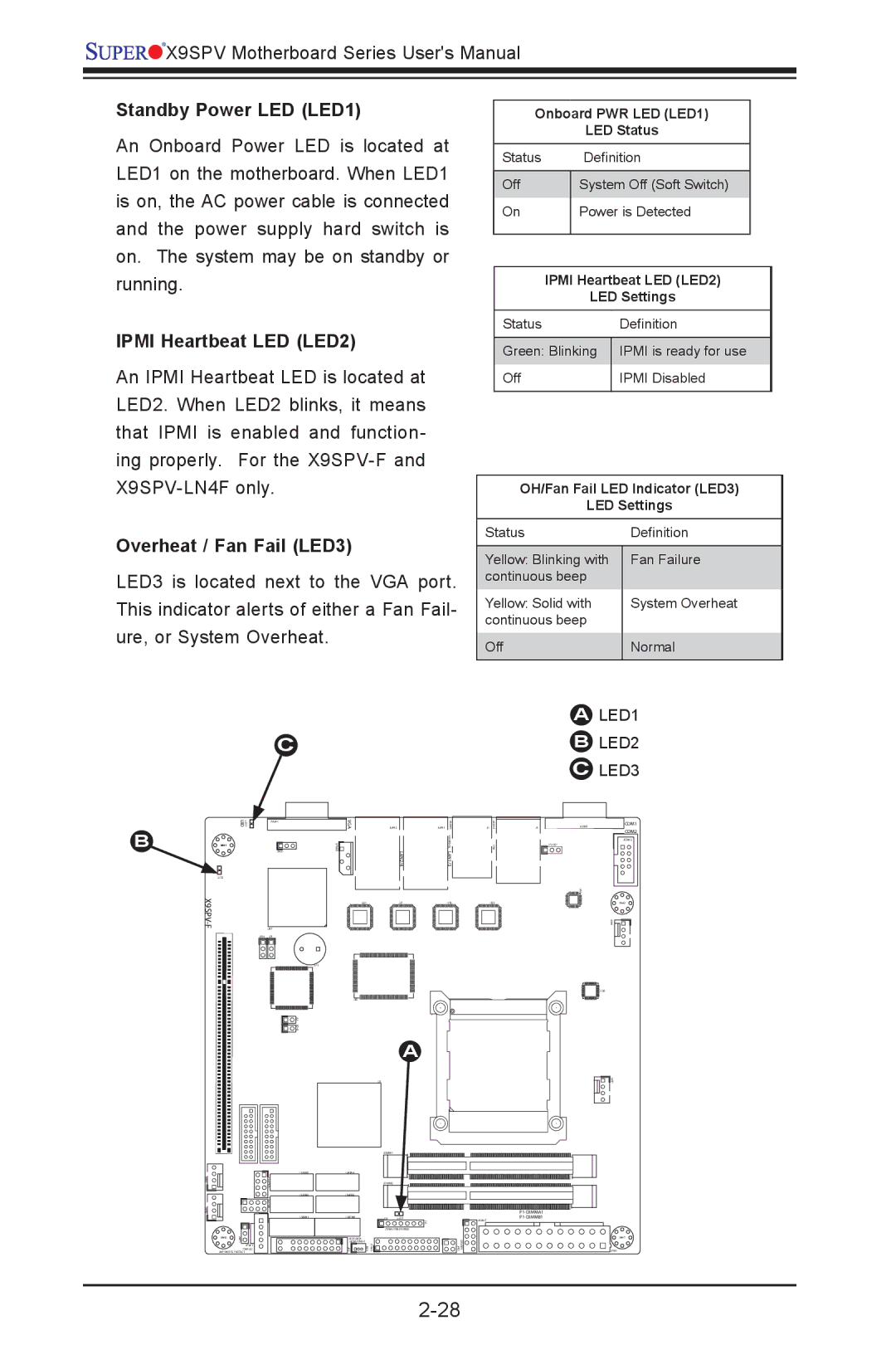
Standby Power LED (LED1)
An Onboard Power LED is located at LED1 on the motherboard. When LED1 is on, the AC power cable is connected and the power supply hard switch is on. The system may be on standby or running.
IPMI Heartbeat LED (LED2)
An IPMI Heartbeat LED is located at LED2. When LED2 blinks, it means that IPMI is enabled and function- ing properly. For the
Overheat / Fan Fail (LED3)
LED3 is located next to the VGA port. This indicator alerts of either a Fan Fail- ure, or System Overheat.
C
Onboard PWR LED (LED1)
LED Status
Status |
| Definition |
|
|
|
|
|
Off |
| System Off (Soft Switch) |
|
On |
| Power is Detected |
|
|
|
|
|
|
|
| |
| IPMI Heartbeat LED (LED2) |
| |
|
| LED Settings |
|
Status |
| Definition |
|
Green: Blinking | IPMI is ready for use |
Off | IPMI Disabled |
|
|
OH/Fan Fail LED Indicator (LED3)
LED Settings
Status | Definition |
|
|
Yellow: Blinking with | Fan Failure |
continuous beep |
|
Yellow: Solid with | System Overheat |
continuous beep |
|
Off | Normal |
|
|
ALED1
BLED2
CLED3
B
| LED3 UID | JVGA1 |
MH4 |
| 1 |
JWD1
LED2
| U57 |
JPB1 | JP1 |
![]() 1 JL JOH1
1 JL JOH1
|
| |
FAN3 |
| |
|
| |
FAN2 |
| |
|
| |
| MH6 | JWP1 |
|
| |
|
| JPI2C1 |
|
| PWR I2C |
| JWP1:WRITE PROTECT | |
VGA | JLAN2 | JLAN1 | USB8/9 |
JIPMB1 |
| LAN2/4 | KB/MOUSE LAN1/3 |
| U21 | U7 | U10 |
SP1
U6
A
| U3 |
|
|
| JDIMM1 |
|
|
|
|
| |
| JDIMM2 |
|
|
|
|
| |
JD1 | LED1 | F6 | |
|
|
| |
| JTPM1:TPM/PORT80 | 1 | |
JSD1:SATA |
|
| J20USB JPK1 |
DOM POWER | PMJT 1 JSD1 |
| |
JF1 |
| ||
J1 | USB4/5 | J3 | JCOM1 | COM1 |
|
|
|
| COM2 |
|
|
|
| JCOM2 |
| IPMI |
| JPUSB1 |
|
|
|
|
| |
|
|
| 0 |
|
|
|
| U6 |
|
| U22 |
|
| MH2 |
|
|
|
| FAN4 |
|
|
|
| U26 |
|
|
|
| FAN1 |
USB6/7
MH7
JPW1