Chapter 1: Introduction
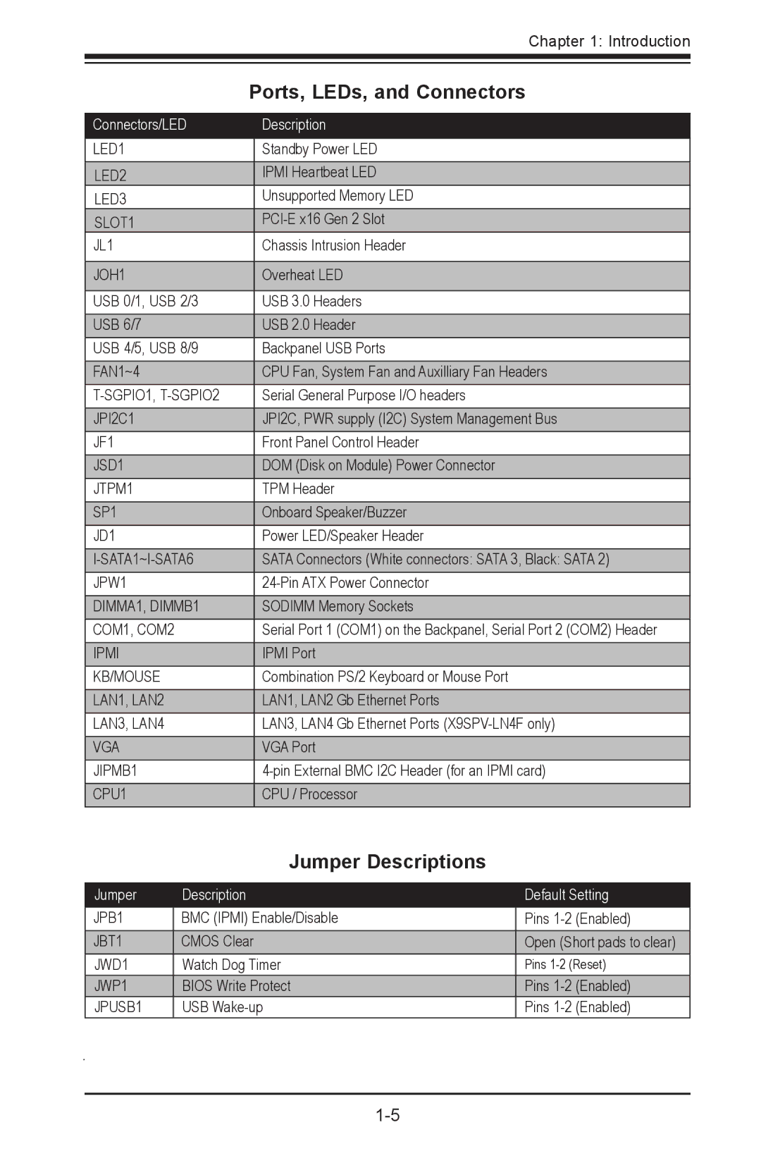
| Ports, LEDs, and Connectors | |
|
|
|
Connectors/LED |
| Description |
|
|
|
LED1 |
| Standby Power LED |
LED2 |
| IPMI Heartbeat LED |
LED3 |
| Unsupported Memory LED |
SLOT1 |
| |
JL1 |
| Chassis Intrusion Header |
|
|
|
JOH1 |
| Overheat LED |
|
|
|
USB 0/1, USB 2/3 |
| USB 3.0 Headers |
USB 6/7 |
| USB 2.0 Header |
USB 4/5, USB 8/9 |
| Backpanel USB Ports |
FAN1~4 |
| CPU Fan, System Fan and Auxilliary Fan Headers |
| Serial General Purpose I/O headers | |
JPI2C1 |
| JPI2C, PWR supply (I2C) System Management Bus |
JF1 |
| Front Panel Control Header |
JSD1 |
| DOM (Disk on Module) Power Connector |
JTPM1 |
| TPM Header |
SP1 |
| Onboard Speaker/Buzzer |
JD1 |
| Power LED/Speaker Header |
| SATA Connectors (White connectors: SATA 3, Black: SATA 2) | |
JPW1 |
| |
DIMMA1, DIMMB1 |
| SODIMM Memory Sockets |
COM1, COM2 |
| Serial Port 1 (COM1) on the Backpanel, Serial Port 2 (COM2) Header |
IPMI |
| IPMI Port |
KB/MOUSE |
| Combination PS/2 Keyboard or Mouse Port |
LAN1, LAN2 |
| LAN1, LAN2 Gb Ethernet Ports |
LAN3, LAN4 |
| LAN3, LAN4 Gb Ethernet Ports |
VGA |
| VGA Port |
JIPMB1 |
| |
CPU1 |
| CPU / Processor |
Jumper Descriptions
Jumper | Description | Default Setting |
JPB1 | BMC (IPMI) Enable/Disable | Pins |
JBT1 | CMOS Clear | Open (Short pads to clear) |
JWD1 | Watch Dog Timer | Pins |
JWP1 | BIOS Write Protect | Pins |
JPUSB1 | USB | Pins |