Chapter 2: Installation
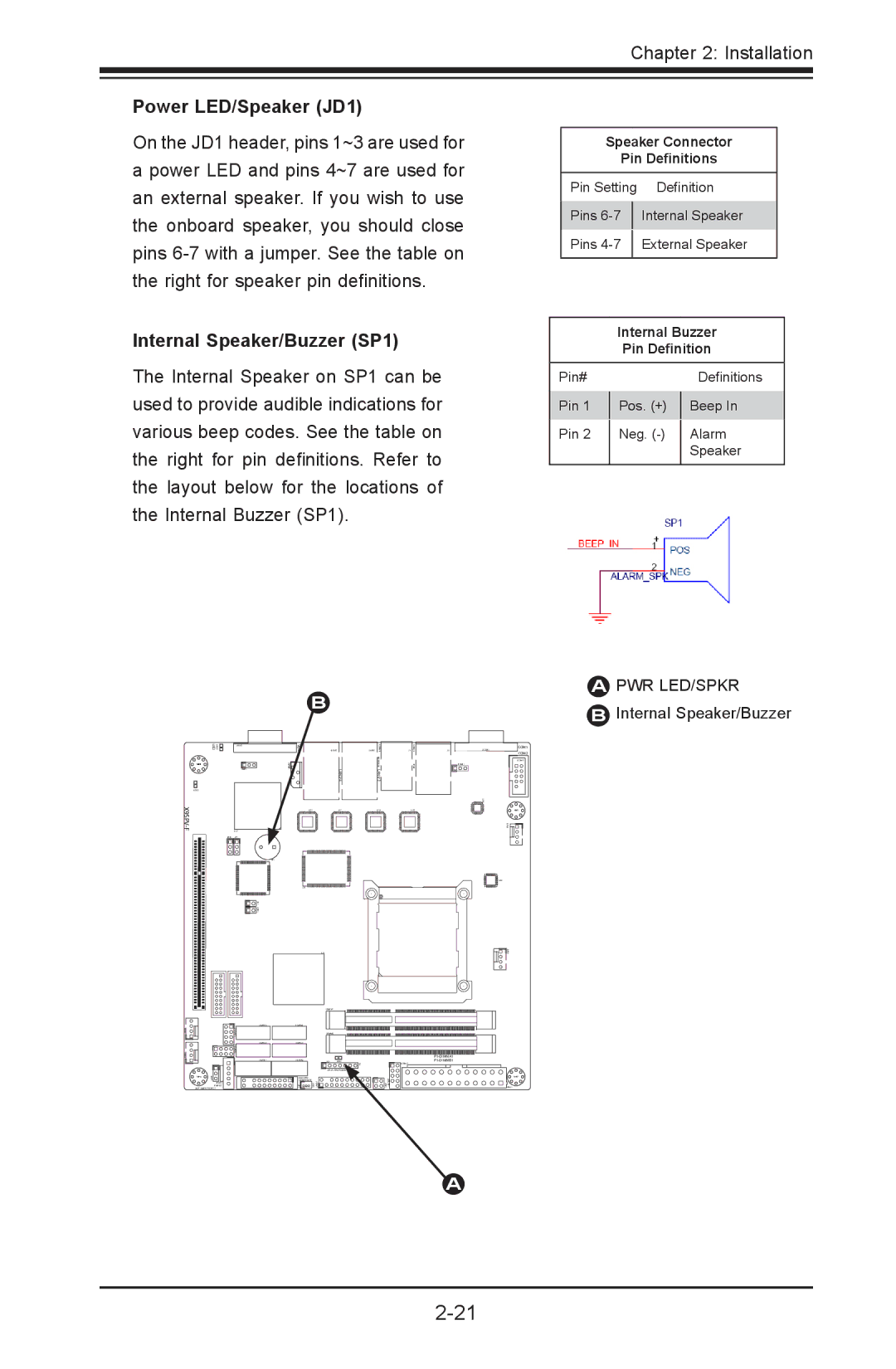
Power LED/Speaker (JD1)
On the JD1 header, pins 1~3 are used for a power LED and pins 4~7 are used for an external speaker. If you wish to use the onboard speaker, you should close pins
Speaker Connector
Pin Definitions
Pin Setting | Definition | |
|
| |
Pins |
| Internal Speaker |
|
|
|
Pins |
| External Speaker |
|
|
|
Internal Speaker/Buzzer (SP1)
The Internal Speaker on SP1 can be used to provide audible indications for various beep codes. See the table on the right for pin definitions. Refer to the layout below for the locations of the Internal Buzzer (SP1).
B
Internal Buzzer
Pin Definition
Pin# |
|
|
| Definitions |
Pin 1 |
| Pos. (+) |
| Beep In |
|
| |||
Pin 2 |
| Neg. |
| Alarm |
|
| |||
|
|
|
| Speaker |
|
|
|
|
|
APWR LED/SPKR
BInternal Speaker/Buzzer
X9SPV-F
UID | JVGA1 |
MH4
LED2
U57
JPB1 JP1
SP1
|
|
| |
|
|
| |
|
|
| |
|
| T- |
|
|
| SGPIO2 |
|
|
|
|
|
|
|
| |
|
|
|
|
MH6
JPI2C1
PWR I2C
JWP1:WRITE PROTECT
VGA | JLAN2 |
| JLAN1 | J1 | J3 | JCOM1 |
|
|
|
|
|
| JPUSB1 |
|
| LAN2/4 | LAN1/3 |
|
|
|
U21 |
| U7 | U10 |
| U22 |
|
|
|
|
|
|
| U26 |
U6 |
|
|
|
|
|
|
| U3 |
|
|
|
|
|
| JDIMM1 |
|
|
|
|
|
|
|
|
|
|
| |
| JDIMM2 |
|
|
|
|
|
|
|
|
|
|
| |
|
|
|
|
|
| |
JD1 | LED1 |
| USB6/7 |
| ||
|
| F6 |
|
|
| |
| JTPM1:TPM/PORT80 |
|
|
|
| |
JSD1:SATA |
|
|
|
|
|
|
DOM POWER |
|
|
|
|
|
|
COM1
COM2
JCOM2
MH2
MH7
JPW1
A