![]()
![]()
![]()
![]()
![]()
![]() X9SPV Motherboard Series User's Manual
X9SPV Motherboard Series User's Manual
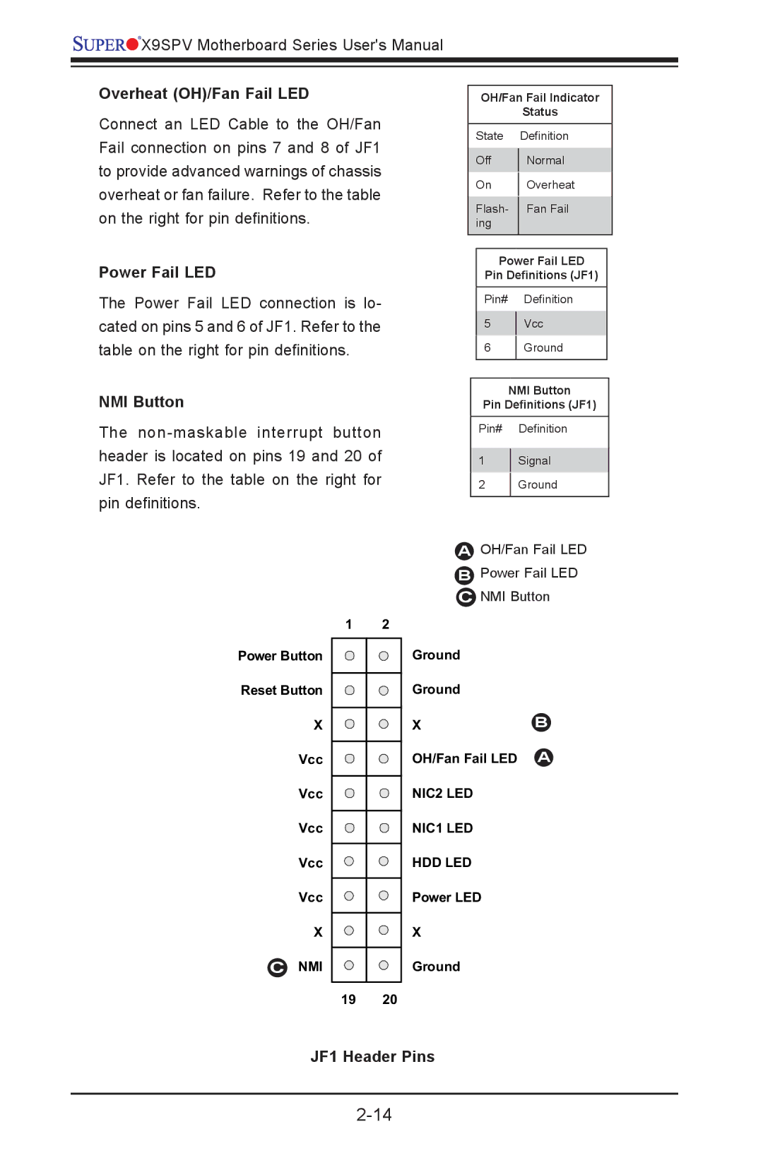
Overheat (OH)/Fan Fail LED
Connect an LED Cable to the OH/Fan Fail connection on pins 7 and 8 of JF1 to provide advanced warnings of chassis overheat or fan failure. Refer to the table on the right for pin definitions.
Power Fail LED
The Power Fail LED connection is lo- cated on pins 5 and 6 of JF1. Refer to the table on the right for pin definitions.
NMI Button
The
OH/Fan Fail Indicator
Status
State Definition
Off | Normal | |
On | Overheat | |
Flash- | Fan Fail | |
ing |
| |
|
|
Power Fail LED
Pin Definitions (JF1)
Pin# Definition
5Vcc
6Ground
NMI Button
Pin Definitions (JF1)
Pin# Definition
1Signal
2Ground
| A OH/Fan Fail LED | |
| B Power Fail LED | |
| C NMI Button | |
1 | 2 |
|
Power Button | Ground |
|
Reset Button | Ground |
|
X | X | B |
Vcc | OH/Fan Fail LED | A |
Vcc | NIC2 LED |
|
Vcc | NIC1 LED |
|
Vcc | HDD LED |
|
Vcc | Power LED |
|
X | X |
|
C NMI | Ground |
|
19 | 20 |
|