Chapter 2: Installation
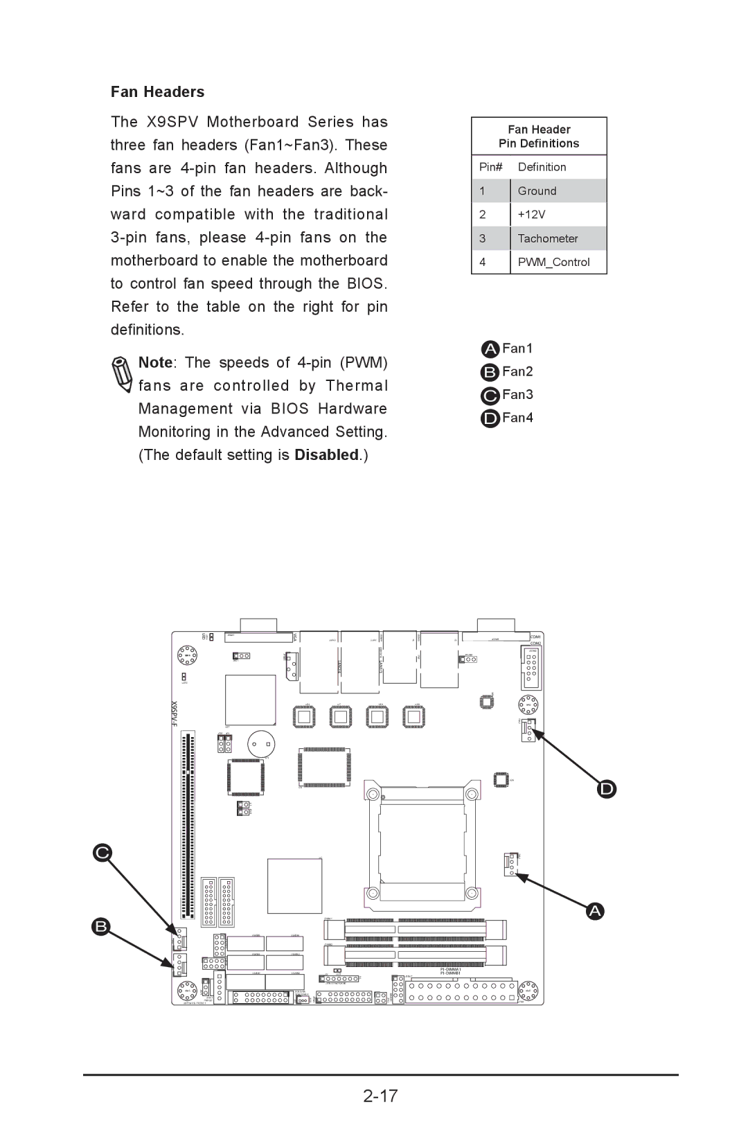
Fan Headers
The X9SPV Motherboard Series has three fan headers (Fan1~Fan3). These fans are
Note: The speeds of ![]() fans are controlled by Thermal Management via BIOS Hardware Monitoring in the Advanced Setting. (The default setting is Disabled.)
fans are controlled by Thermal Management via BIOS Hardware Monitoring in the Advanced Setting. (The default setting is Disabled.)
Fan Header
Pin Definitions
Pin# Definition
1Ground
2+12V
3Tachometer
4PWM_Control
AFan1
BFan2
CFan3
DFan4
| LED3 UID | JVGA1 |
MH4 |
| 1 |
JWD1
LED2
| U57 |
JPB1 | JP1 |
1 JL JOH1
VGA
JIPMB1![]()
![]()
U21
SP1
U6
JLAN2 |
| JLAN1 |
| LAN2/4 | |
| U7 | |
|
|
|
|
|
|
USB8/9 KB/MOUSE LAN1/3
U10
J1 | USB4/5 |
|
| IPMI |
|
|
| |
|
|
|
U22
J3 | JCOM1 | COM1 | |
COM2 | |||
|
| ||
|
| JCOM2 | |
| JPUSB1 |
| |
| 0 |
| |
| U6 |
| |
|
| MH2 | |
|
| FAN4 |
U26 | D |
|
C
B
FAN3FAN2
MH6 | JWP1 |
|
JPI2C1
PWR I2C
JWP1:WRITE PROTECT
JSD1:SATA
DOM POWER
JF1 | JSD1 |
U3
JDIMM1
JDIMM2
JD1 LED1
F6
JTPM1:TPM/PORT80
PMJT 1
1 J20USB JPK1
USB6/7
![]()
![]()
![]() FAN1
FAN1
A
MH7
JPW1