![]()
![]()
![]()
![]()
![]()
![]() X9SPV Motherboard Series User's Manual
X9SPV Motherboard Series User's Manual
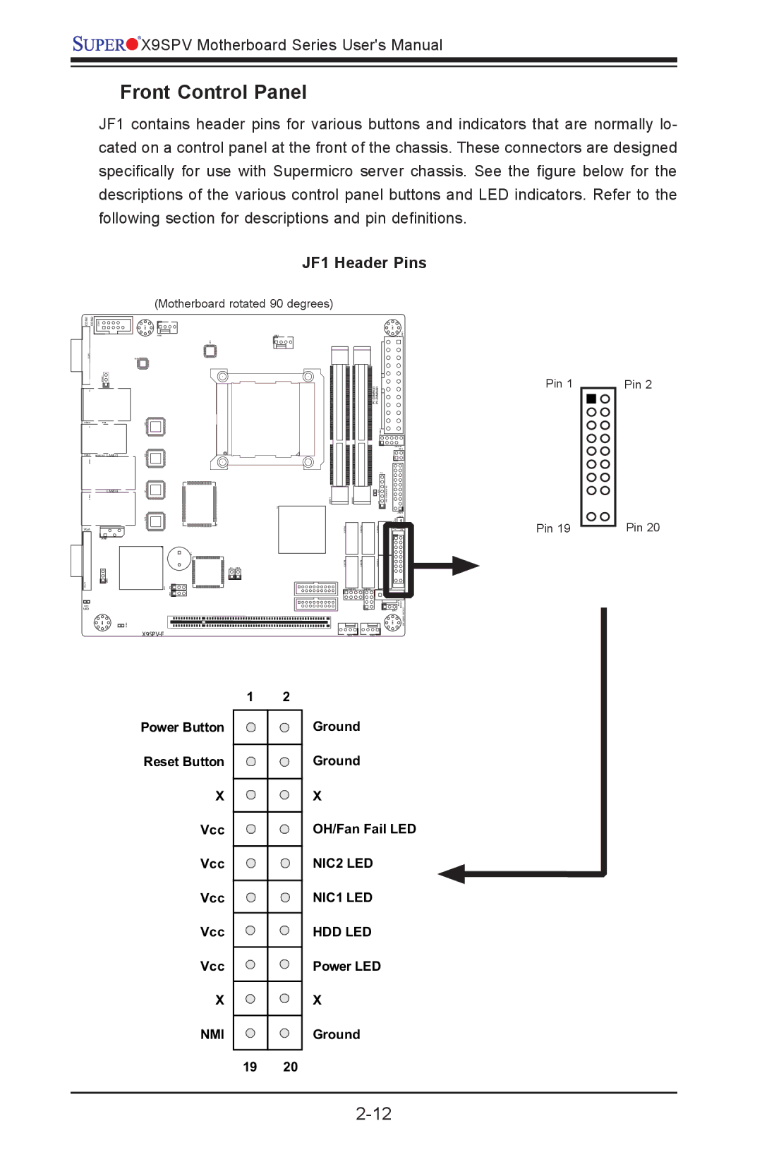
Front Control Panel
JF1 contains header pins for various buttons and indicators that are normally lo- cated on a control panel at the front of the chassis. These connectors are designed specifically for use with Supermicro server chassis. See the figure below for the descriptions of the various control panel buttons and LED indicators. Refer to the following section for descriptions and pin definitions.
JF1 Header Pins
COM1 COM2 | JCOM2 | ||
|
|
|
|
|
|
|
|
JCOM1 |
|
|
|
| JPUSB1 | ||
(Motherboard rotated 90 degrees)
MH2 |
|
FAN4 | FAN1 |
| U26 |
U60 |
|
MH7 JPW1
Pin 1
Pin 2
J3 |
|
|
USB4/5 | IPMI |
|
J1 |
|
|
USB8/9 | KB/MOUSE | LAN1/3 |
JLAN1 |
|
|
|
| LAN2/4 |
JLAN2 |
|
|
VGA |
|
|
| JIPMB1 | |
JVGA1 | 1 | JWD1 |
LED3 |
|
|
UID |
|
|
U22 |
|
U10 |
|
U7 |
|
| JDIMM1 |
| U3 |
U21 |
|
| U6 |
| SP1 |
| JL1 JOH1 |
U57 | JP1 |
| JPB1 |
JDIMM2
USB6/7
| J20USB1 | |
| JPK1 | |
| F6 |
|
LED1 | JTPM1:TPM/PORT80 |
|
JD1 |
| |
| JTPM1 | |
| JSD1 | |
SATA0 | JSD1:SATA DOM POWER | JF1 |
I- |
|
|
|
| |
|
| |
| JWP1 | PWR I2C PROTECT |
| JPI2C1 | |
Pin 19
Pin 20
MH4 | LED2 |
X9SPV-F
MH6 | JWP1:WRITE |
FAN3FAN2
1 2
Power Button
Reset Button
X |
|
Vcc |
|
Vcc |
|
Vcc |
|
Vcc |
|
Vcc |
|
X |
|
NMI |
|
19 | 20 |
Ground
Ground
X
OH/Fan Fail LED
NIC2 LED
NIC1 LED
HDD LED
Power LED
X
Ground