![]()
![]()
![]() X9SPV Motherboard Series User's Manual
X9SPV Motherboard Series User's Manual
2-5 Connecting Cables
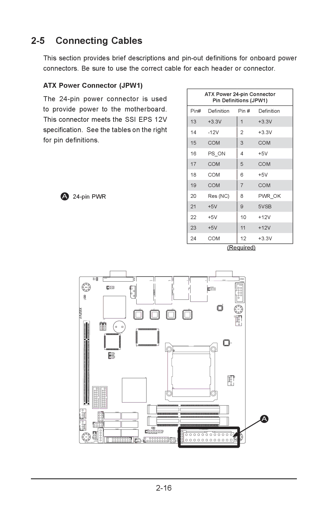
This section provides brief descriptions and
ATX Power Connector (JPW1)
The
A24-pin PWR
ATX Power
Pin Definitions (JPW1)
Pin# | Definition | Pin # | Definition |
13 | +3.3V |
| +3.3V |
1 | |||
14 |
| +3.3V | |
2 | |||
15 | COM |
| COM |
3 | |||
16 | PS_ON |
| +5V |
4 | |||
17 | COM |
| COM |
5 | |||
18 | COM |
| +5V |
6 | |||
19 | COM |
| COM |
7 | |||
20 | Res (NC) |
| PWR_OK |
8 | |||
21 | +5V |
| 5VSB |
9 | |||
22 | +5V | 10 | +12V |
23 | +5V | 11 | +12V |
24 | COM | 12 | +3.3V |
(Required)
LED3
UID
MH4
LED2
JVGA1
1
JWD1
VGA
JIPMB1![]()
![]()
JLAN2
LAN2/4
JLAN1
USB8/9 KB/MOUSE LAN1/3
J1
![]() USB4/5IPMI
USB4/5IPMI
J3
JCOM1
JPUSB1
0 U6
COM1
COM2
JCOM2
FAN3
U57
JPB1 JP1
SP1
![]() 1 JL JOH1
1 JL JOH1
![]() I-SATA5
I-SATA5
U21
U6
U7 |
| U10 |
| U22 |
|
|
|
|
|
|
|
|
|
|
U3
JDIMM1
JDIMM2
MH2
FAN4
U26
![]()
![]()
![]() FAN1
FAN1
A
FAN2
MH6 | JWP1 |
|
JPI2C1
PWR I2C
JWP1:WRITE PROTECT
JSD1:SATA
DOM POWER
JF1 | JSD1 |
|
|
| |
JD1 | LED1 |
| |
| F6 |
| USB6/7 |
JTPM1:TPM/PORT80 | 1 |
| |
|
| J20USB JPK1 | MH7 |
PMJT 1 |
| JPW1 | |