Chapter 2: Installation
2-8 Serial ATA and HDD Connections
Note the following conditions when connecting the Serial ATA and hard disk drive cables:
•Be sure to use the correct cable for each connector. Refer to Page
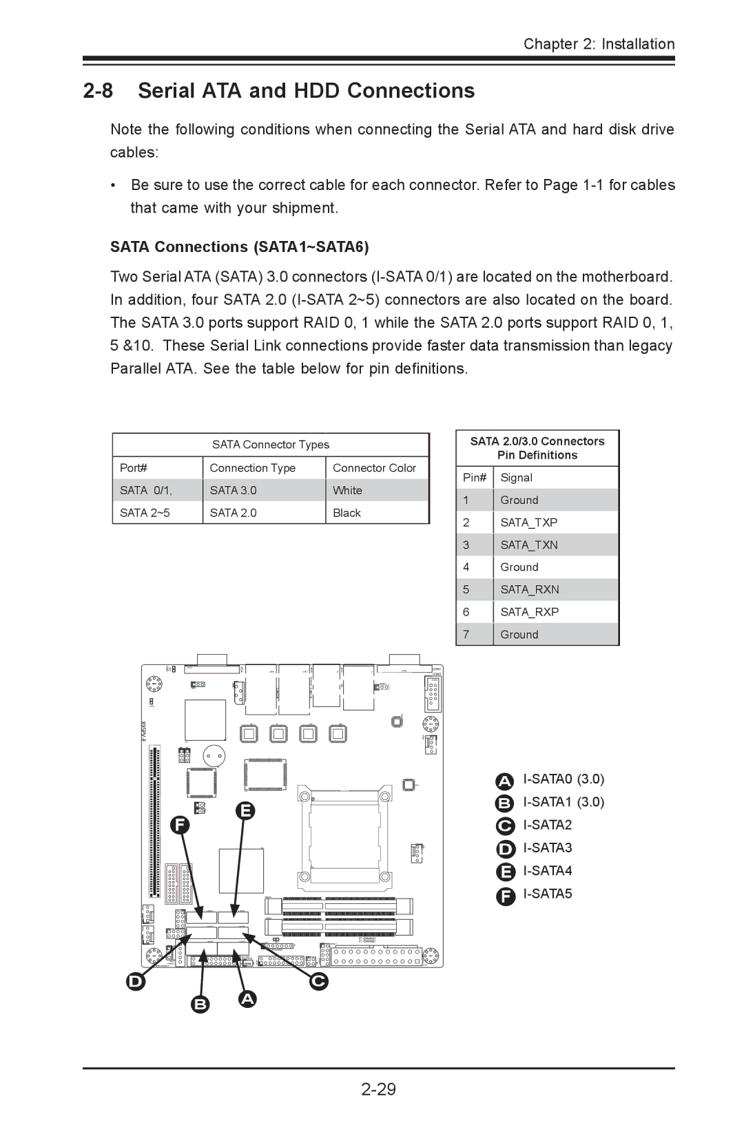
SATA Connections (SATA1~SATA6)
Two Serial ATA (SATA) 3.0 connectors
SATA Connector Types
Port# | Connection Type | Connector Color | |
SATA 0/1, | SATA 3.0 | White | |
SATA 2~5 | SATA 2.0 | Black | |
|
|
|
SATA 2.0/3.0 Connectors
Pin Definitions
Pin# Signal
1Ground
2SATA_TXP
3SATA_TXN
4Ground
5SATA_RXN
6SATA_RXP
7 Ground
LED3 UID | JVGA1 |
| VGA |
|
| USB8/9 |
| USB4/5 |
|
| JLAN2 | JLAN1 | J1 | ||||
MH4 | 1 |
| JIPMB1 | LAN2/4 |
| LAN1/3KB/MOUSE |
| IPMI |
| JWD1 |
|
|
|
|
|
|
|
LED2 |
|
|
|
|
|
|
|
|
| U57 |
| U21 | U7 |
| U10 |
| U22 |
JPB1 | JP1 |
|
|
|
|
|
|
|
|
|
| SP1 |
|
|
|
|
|
|
|
| U6 |
|
|
|
|
|
|
| 1 JL | E |
|
|
|
|
|
|
| JOH1 |
|
|
|
|
|
|
F |
|
|
|
|
|
|
|
|
J3
JCOM1
JPUSB1
0 U6
FAN4
U26
COM1
COM2
JCOM2
MH2
A |
B |
C |
FAN3FAN2
D
| T- | |
| SGPIO2 |
|
|
| |
MH6 | JWP1 |
|
|
| |
| JPI2C1 |
|
| PWR I2C |
|
JWP1:WRITE PROTECT |
| |
B
U3
JDIMM1
JDIMM2
JD1 | LED1 | |
|
| F6 |
| JTPM1:TPM/PORT80 | |
JSD1:SATA |
|
DOM POWER | PMJT 1 JSD1 |
JF1 |
A
1 J20USB JPK1
C
USB6/7
![]()
![]()
![]() FAN1
FAN1
MH7
JPW1
D |
E![]()
![]()
![]()
![]()