TANDBERG 7000 MXP
2.2 Connecting Cables
1. Power cable
Connect the system power cable to the correct country variant of the power cable. Connect this cable to an electrical distribution socket.
2. Microphone cable
Connect the microphone cables to the microphones.
3. DNAM Audio Module - audio cable
Connect the RCA cable coming out of the bottom of the base to Audio out 1 on the codec.
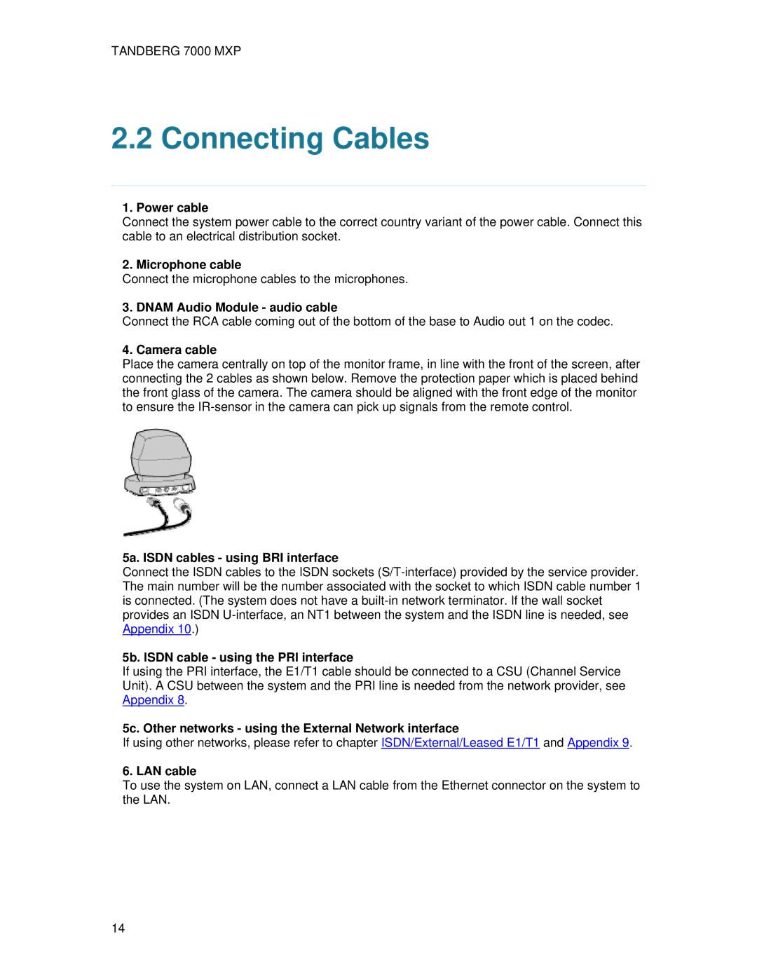
4. Camera cable
Place the camera centrally on top of the monitor frame, in line with the front of the screen, after connecting the 2 cables as shown below. Remove the protection paper which is placed behind the front glass of the camera. The camera should be aligned with the front edge of the monitor to ensure the
5a. ISDN cables - using BRI interface
Connect the ISDN cables to the ISDN sockets
5b. ISDN cable - using the PRI interface
If using the PRI interface, the E1/T1 cable should be connected to a CSU (Channel Service Unit). A CSU between the system and the PRI line is needed from the network provider, see Appendix 8.
5c. Other networks - using the External Network interface
If using other networks, please refer to chapter ISDN/External/Leased E1/T1 and Appendix 9.
6. LAN cable
To use the system on LAN, connect a LAN cable from the Ethernet connector on the system to the LAN.
14