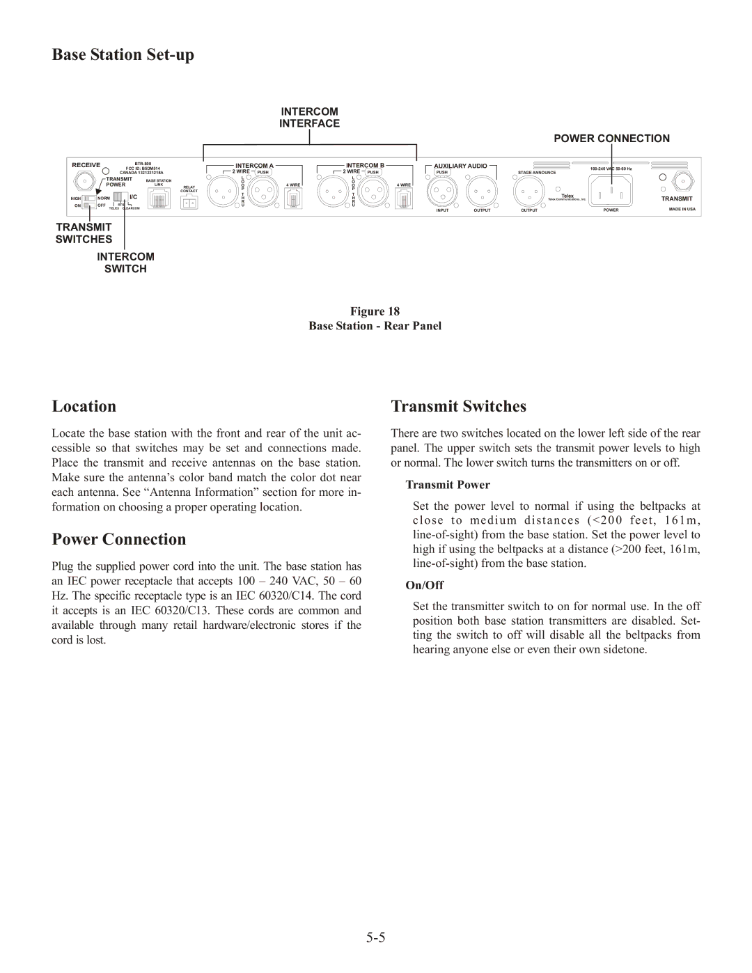
Base Station Set-up
INTERCOM
INTERFACE
|
|
|
|
|
|
|
|
|
|
| POWER CONNECTION | |
RECEIVE |
| INTERCOM A | INTERCOM B | AUXILIARY AUDIO |
|
|
| |||||
FCC ID: B5DM514 |
|
|
| |||||||||
|
| CANADA 1321231218A |
| 2 WIRE | PUSH | 2 WIRE PUSH | PUSH |
| STAGE ANNOUNCE |
| ||
| TRANSMIT | BASE STATION |
| L |
| L |
|
|
|
|
| |
|
| O | 4 WIRE | O | 4 WIRE |
|
|
|
| |||
| POWER | LINK | RELAY | O | O |
|
|
|
| |||
|
|
|
| P |
| P |
|
|
|
|
| |
|
|
|
| CONTACT |
|
|
|
|
|
| ||
|
| I/C |
| T |
| T |
|
|
| Telex |
| |
HIGH | NORM |
|
|
|
|
|
| TRANSMIT | ||||
|
| R |
| R |
|
|
| Telex Communications, Inc. | ||||
|
| H |
| H |
|
|
|
| ||||
ON | OFF | RTS |
|
| U |
| U |
|
|
|
|
|
| TELEX CLEARCOM |
|
|
|
|
| INPUT | OUTPUT | OUTPUT | POWER | MADE IN USA | |
|
|
|
|
|
|
|
| |||||
TRANSMIT
SWITCHES
INTERCOM
SWITCH
Figure 18
Base Station - Rear Panel
Location
Locate the base station with the front and rear of the unit ac- cessible so that switches may be set and connections made. Place the transmit and receive antennas on the base station. Make sure the antenna’s color band match the color dot near each antenna. See “Antenna Information” section for more in- formation on choosing a proper operating location.
Power Connection
Plug the supplied power cord into the unit. The base station has an IEC power receptacle that accepts 100 – 240 VAC, 50 – 60 Hz. The specific receptacle type is an IEC 60320/C14. The cord it accepts is an IEC 60320/C13. These cords are common and available through many retail hardware/electronic stores if the cord is lost.
Transmit Switches
There are two switches located on the lower left side of the rear panel. The upper switch sets the transmit power levels to high or normal. The lower switch turns the transmitters on or off.
Transmit Power
Set the power level to normal if using the beltpacks at c l o se t o me d i u m d i s t a n ce s ( <2 0 0 f e e t, 1 6 1 m,
On/Off
Set the transmitter switch to on for normal use. In the off position both base station transmitters are disabled. Set- ting the switch to off will disable all the beltpacks from hearing anyone else or even their own sidetone.