Controls and Connections - Rear Panel
1 | 12 |
RECEIVE |
|
| |||
| FCC ID: B5DM514 |
| |||
|
| CANADA 1321231218A |
| ||
|
| TRANSMIT | BASE STATION |
| |
|
| POWER |
| LINK | RELAY |
|
|
| I/C |
| CONTACT |
HIGH | NORM |
|
| ||
ON | OFF | RTS |
|
|
|
|
| TELEX CLEARCOM |
|
| |
INTERCOM A
2 WIRE | PUSH |
L |
|
O | 4 WIRE |
O | |
P |
|
T |
|
H |
|
R |
|
U |
|
INTERCOM B
2 WIRE | PUSH |
L |
|
O | 4 WIRE |
O | |
P |
|
T |
|
H |
|
R |
|
U |
|
AUXILIARY AUDIO
PUSH
INPUTOUTPUT
STAGE ANNOUNCE
Telex
Telex Communications, Inc.
OUTPUT | POWER |
TRANSMIT
MADE IN USA
2 | 3 | 4 | 5 | 6 | 7 | 8 | 9 | 10 | 11 |
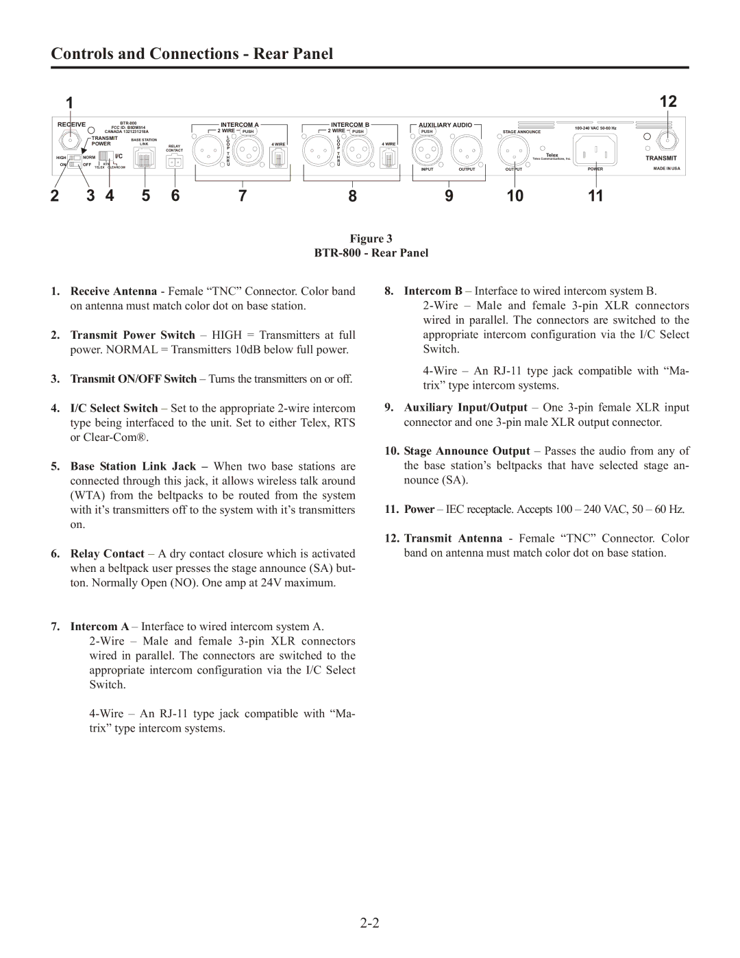
Figure 3
BTR-800 - Rear Panel
1.Receive Antenna - Female “TNC” Connector. Color band on antenna must match color dot on base station.
2.Transmit Power Switch – HIGH = Transmitters at full power. NORMAL = Transmitters 10dB below full power.
3.Transmit ON/OFF Switch – Turns the transmitters on or off.
4.I/C Select Switch – Set to the appropriate
5.Base Station Link Jack – When two base stations are connected through this jack, it allows wireless talk around (WTA) from the beltpacks to be routed from the system with it’s transmitters off to the system with it’s transmitters on.
6.Relay Contact – A dry contact closure which is activated when a beltpack user presses the stage announce (SA) but- ton. Normally Open (NO). One amp at 24V maximum.
7.Intercom A – Interface to wired intercom system A.
8.Intercom B – Interface to wired intercom system B.
9.Auxiliary Input/Output – One
10.Stage Announce Output – Passes the audio from any of the base station’s beltpacks that have selected stage an- nounce (SA).
11.Power – IEC receptacle. Accepts 100 – 240 VAC, 50 – 60 Hz.
12.Transmit Antenna - Female “TNC” Connector. Color band on antenna must match color dot on base station.