Dual Listen Functionality
The base stations's main audio board has the option of placing additional parts to enable dual listen. Dual listen allows the mixing of the intercom channels. The mixing will occur lo- cally, within the base station, and is only heard on that base station's beltpacks. The user will have the ability to enable/dis- able the mix of I/C A into I/C B or vise versa. If you have
They will also have the ability to control the level of the mix
Board |
|
|
|
|
|
|
|
|
|
|
Designator |
| Description and Function | Value |
|
| Manufacturers, Part No. |
| |||
|
|
|
|
|
|
|
| |||
VR5, VR6 |
| Potentiometers |
| 20kW - 25kW |
| Bourns, |
| |||
|
| VR5 = Controls I/C A into I/C B Mix |
|
| CTS, U262R253B |
| ||||
|
| VR6 = Controls I/C B into I/C A Mix |
|
| Piher, |
| ||||
|
|
|
|
|
|
|
| |||
S6, S7 |
| Switches |
| SPDT |
|
| ||||
|
| S6 = Enable/Disable I/C A into I/C B Mix |
|
|
| |||||
|
| S7 = Enable/Disable I/C B into I/C A Mix |
|
| Alcoswitch, TSS11DGPC |
| ||||
|
|
|
|
|
|
|
|
|
|
|
|
|
|
| Table 1 |
|
|
|
|
|
|
|
| Parts to be Installed by User to Enable Dual Listen |
|
|
|
| ||||
|
|
|
|
|
|
|
|
|
|
|
|
| Board |
|
|
|
|
|
|
|
|
|
| Designator |
| Description and Function |
| Value |
|
| ||
|
|
|
|
|
|
|
|
|
|
|
|
| R295 |
| Resistor, Default if mix components not installed |
| 10k |
|
| ||
|
| R296 |
| Resistor, Default if mix components not installed |
| 10k |
|
| ||
|
|
|
|
|
|
|
|
|
|
|
Table 2
Parts to be Removed by User to Enable Dual Listen
The listed manufactures and part numbers in Table 1 are those that the audio board was laid out for and thus the hole pattern used. Several of these parts may be found at
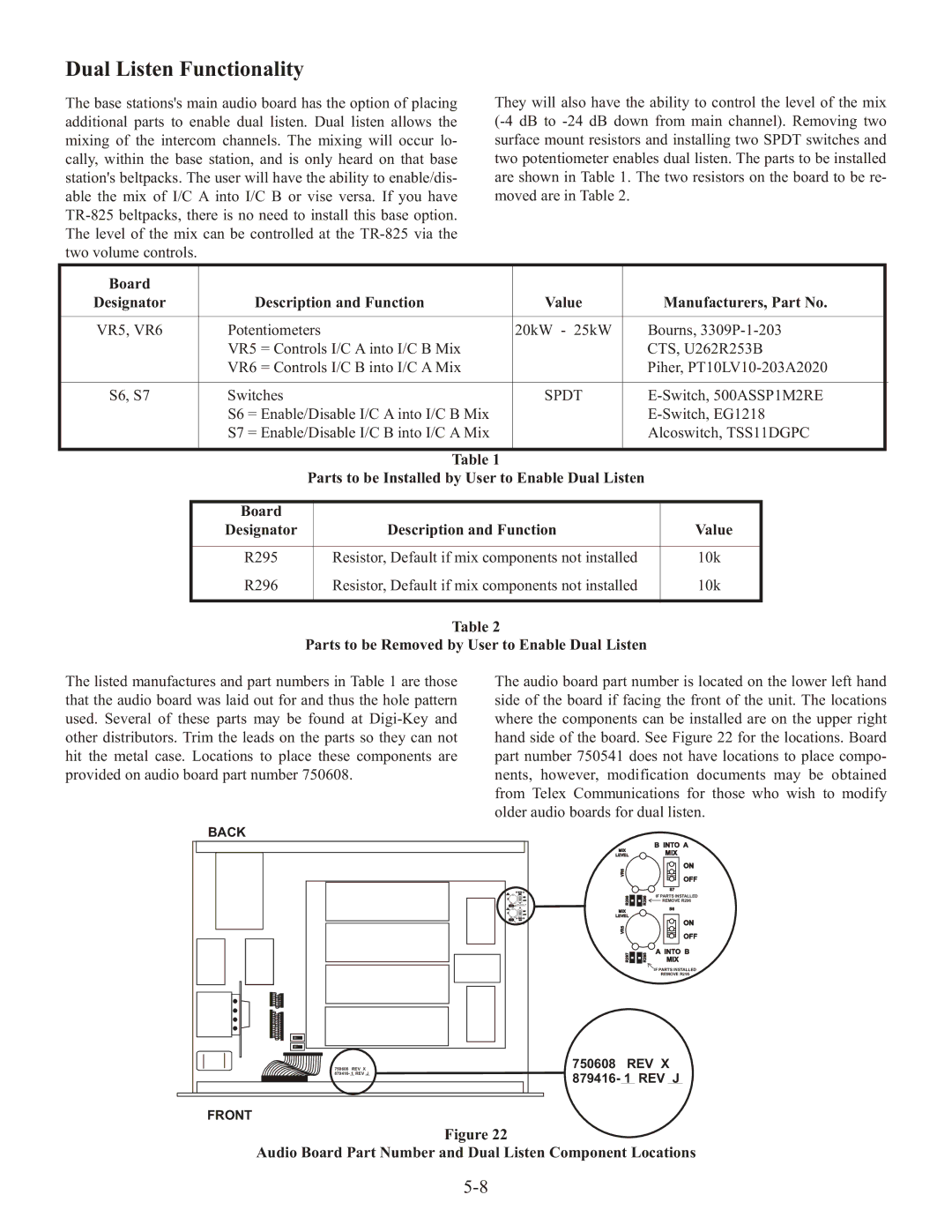
The audio board part number is located on the lower left hand side of the board if facing the front of the unit. The locations where the components can be installed are on the upper right hand side of the board. See Figure 22 for the locations. Board part number 750541 does not have locations to place compo- nents, however, modification documents may be obtained from Telex Communications for those who wish to modify older audio boards for dual listen.
BACK |
|
|
|
| B INTO A |
|
|
| MIX |
| |
|
|
|
| MIX | |
|
| LEVEL |
| ||
|
|
| VR6 |
| ON |
|
|
|
| OFF | |
|
|
|
|
| |
| B INTO A |
|
|
| S7 |
| MIX |
| R298 | R296 | IF PARTS INSTALLED |
| ON |
| |||
| OFF |
| REMOVE R296 | ||
|
|
| |||
| ON |
| MIX |
| S6 |
| OFF | LEVEL |
|
| |
| A INTO B |
| ON | ||
| MIX |
|
|
| |
|
|
| VR5 |
| |
|
|
|
| OFF | |
|
|
|
|
| |
|
|
| R297 | R295 | A INTO B |
|
|
| MIX | ||
|
|
|
|
| IF PARTS INSTALLED |
|
|
|
|
| REMOVE R295 |
750608 | REV X | 750608 | REV X | ||
879416- 1 REV J | 879416- 1 REV J | ||||
|
| ||||
FRONT |
|
|
|
|
|
Figure 22
