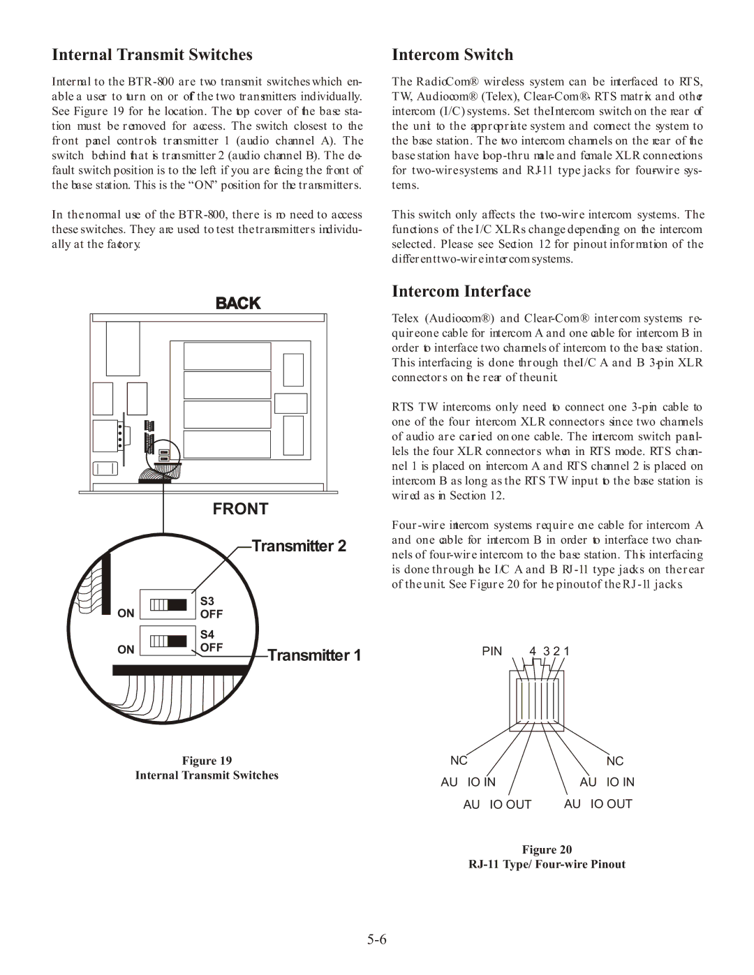
Internal Transmit Switches
Internal to the
In the normal use of the
Intercom Switch
The RadioCom® wireless system can be interfaced to RTS, TW, Audiocom® (Telex),
This switch only affects the
BACK |
FRONT |
Transmitter 2
ON |
|
|
|
|
|
|
| S3 |
|
|
|
|
|
|
| ||
|
|
|
|
|
|
| OFF | |
|
|
|
|
|
|
| ||
|
|
|
|
|
|
|
| S4 |
|
|
|
|
|
|
|
| |
ON |
|
|
|
|
|
|
| OFF |
|
|
|
|
|
|
| ||
|
|
|
|
|
|
|
| Transmitter 1 |
|
|
|
|
|
|
|
|
Figure 19
Internal Transmit Switches
Intercom Interface
Telex (Audiocom®) and
RTS TW intercoms only need to connect one
PIN 6 5 4 3 2 1
NC | NC |
AUDIO IN - | AUDIO IN + |
AUDIO OUT - | AUDIO OUT + |
Figure 20