Controls and Connections - Rear Panel
1 |
SET | MENU |
(1) Microphone
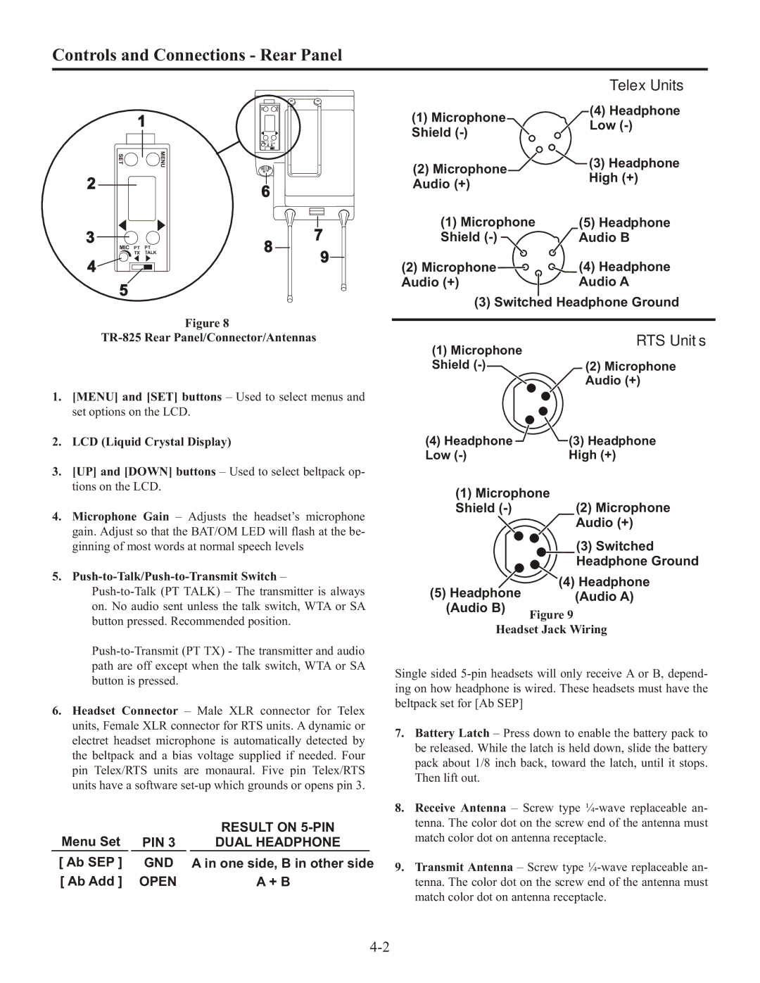
Telex Units
(4) Headphone
MIC | PT | PT |
| TX | TALK |
Shield
Low
SET | MENU |
(2) Microphone
![]() (3) Headphone
(3) Headphone
2 |
6
Audio (+)
High (+)
3 | MIC PT PT |
| TX TALK |
4 |
|
| 5 |
7
8
9
(1) Microphone | (5) Headphone |
Shield | Audio B |
(2) Microphone | (4) Headphone |
Audio (+) | Audio A |
(3) Switched Headphone Ground
Figure 8
TR-825 Rear Panel/Connector/Antennas
1.[MENU] and [SET] buttons – Used to select menus and set options on the LCD.
2.LCD (Liquid Crystal Display)
3.[UP] and [DOWN] buttons – Used to select beltpack op- tions on the LCD.
4.Microphone Gain – Adjusts the headset’s microphone gain. Adjust so that the BAT/OM LED will flash at the be- ginning of most words at normal speech levels
5.Push-to-Talk/Push-to-Transmit Switch –
6.Headset Connector – Male XLR connector for Telex units, Female XLR connector for RTS units. A dynamic or electret headset microphone is automatically detected by the beltpack and a bias voltage supplied if needed. Four pin Telex/RTS units are monaural. Five pin Telex/RTS units have a software
Menu Set |
|
|
| RESULT ON | |
| PIN 3 |
| DUAL HEADPHONE |
| |
[ Ab SEP ] |
| GND |
| A in one side, B in other side | |
[ Ab Add ] |
| OPEN |
| A + B | |
RTS Units
(1) Microphone
Shield
Audio (+)
(4) Headphone | (3) Headphone |
Low | High (+) |
(1) Microphone
Shield
Audio (+)
(3) Switched
Headphone Ground
(4) Headphone
(5) Headphone (Audio A)
(Audio B)
Figure 9
Headset Jack Wiring
Single sided
7.Battery Latch – Press down to enable the battery pack to be released. While the latch is held down, slide the battery pack about 1/8 inch back, toward the latch, until it stops. Then lift out.
8.Receive Antenna – Screw type
9.Transmit Antenna – Screw type