Section
2
BTR-800 Base Station
Controls and Connections - Front Panel
1 2
MENU
ClearScanTM
SET
3 | 4 | 5 | 6 | 7 | 8 | 9 |
| 11 |
| |
10 | 12 | |||||||||
|
|
|
|
|
|
| ||||
RadioComä | UP |
| 2 WIRE | 2 WIRE |
| ON/O.M. | VOLUME | TALK/O.M. |
| |
|
|
| IN | IN | IN |
|
| |||
|
|
|
| A |
|
| ||||
|
| 1 2 3 4 | 4 WIRE | 4 WIRE |
|
| MIC GAIN |
| ||
|
|
|
|
|
| |||||
|
| OUT | OUT | OUT |
| B |
|
| ||
|
|
|
|
|
|
|
| |||
|
|
| SELECT | SELECT |
| ON/OFF |
|
|
| |
COPY | DOWN | PORTABLE STATION CONNECT | INTERCOM A | INTERCOM B | AUXILIARY | SELECT | TALK |
| ||
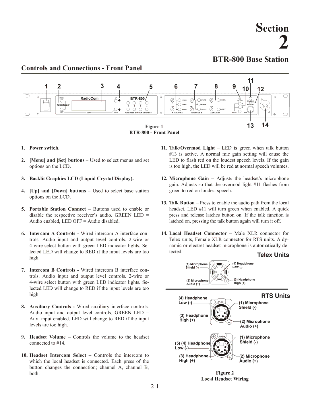
| Figure 1 | 13 14 | |
|
| ||
1. | Power switch. | 11. | Talk/Overmod Light – LED is green when talk button |
|
|
| #13 is active. A normal mic gain setting will cause the |
2. | [Menu] and [Set] buttons – Used to select menus and set |
| LED to flash red on the loudest speech levels. If the gain |
| options on the LCD. |
| is too high, the LED will be red at normal speech volumes. |
3. | Backlit Graphics LCD (Liquid Crystal Display). | 12. | Microphone Gain – Adjusts the headset’s microphone |
|
|
| gain. Adjusts so that the overmod light #11 flashes from |
4. | [Up] and [Down] buttons – Used to select base station |
| green to red on loudest speech. |
| options on the LCD. |
|
|
5.Portable Station Connect – Buttons used to enable or disable the respective receiver’s audio. GREEN LED = Audio enabled, LED OFF = Audio disabled.
6.Intercom A Controls - Wired intercom A interface con- trols. Audio input and output level controls.
7.Intercom B Controls - Wired intercom B interface con- trols. Audio input and output level controls.
8.Auxiliary Controls - Wired auxiliary interface controls. Audio input and output level controls. GREEN LED = Aux. input enabled. LED will change to RED if the input levels are too high.
9.Headset Volume – Controls the volume to the headset connected to #14.
10.Headset Intercom Select – Controls the intercom to which the local headset is connected. Each press of the button changes the connection; channel A, channel B, both.
13.Talk Button – Press to enable the audio path from the local headset. LED #11 will turn green when enabled. A quick press and release latches button on. If the talk function is latched on, pressing the talk button again will turn it off.
14.Local Headset Connector – Male XLR connector for Telex units, Female XLR connector for RTS units. A dy- namic or electret headset microphone is automatically de- tected.
Telex Units
(1) Microphone |
| (4) Headphone |
Shield |
| Low |
(2) Microphone |
| (3) Headphone |
Audio (+) |
| High (+) |
(4) Headphone |
| RTS Units |
| (1) Microphone | |
Low | PUSH | |
|
| |
|
| Shield |
(3) Headphone |
|
|
High (+) |
| (2) Microphone |
|
| Audio (+) |
| PUSH | (1) Microphone |
|
| |
(5) (4) Headphone |
| Shield |
Low |
|
|
(3) Headphone |
| (2) Microphone |
High (+) |
| Audio (+) |
Figure 2