All installations and services must be performed by qualified service personnel.
Typically, control wiring between the outdoor appliance and the indoor thermostat, and if used, electronic air cleaner or humidifier, will be required. Field wiring of control circuits should consist of copper conductors rated for at least 240 VAC with an insulation temperature rating conforming to Type T wire, 35°C temperature rise. Depending upon code requirements, rigid or flexible conduit is recommended, and may be required. Make connections between the thermostat, and electronic air cleaner or humidifier (if used), and the fan control module, inside the burner compartment. Consult the wiring diagram for the appropriate connection points on the thermostat and the fan control module.
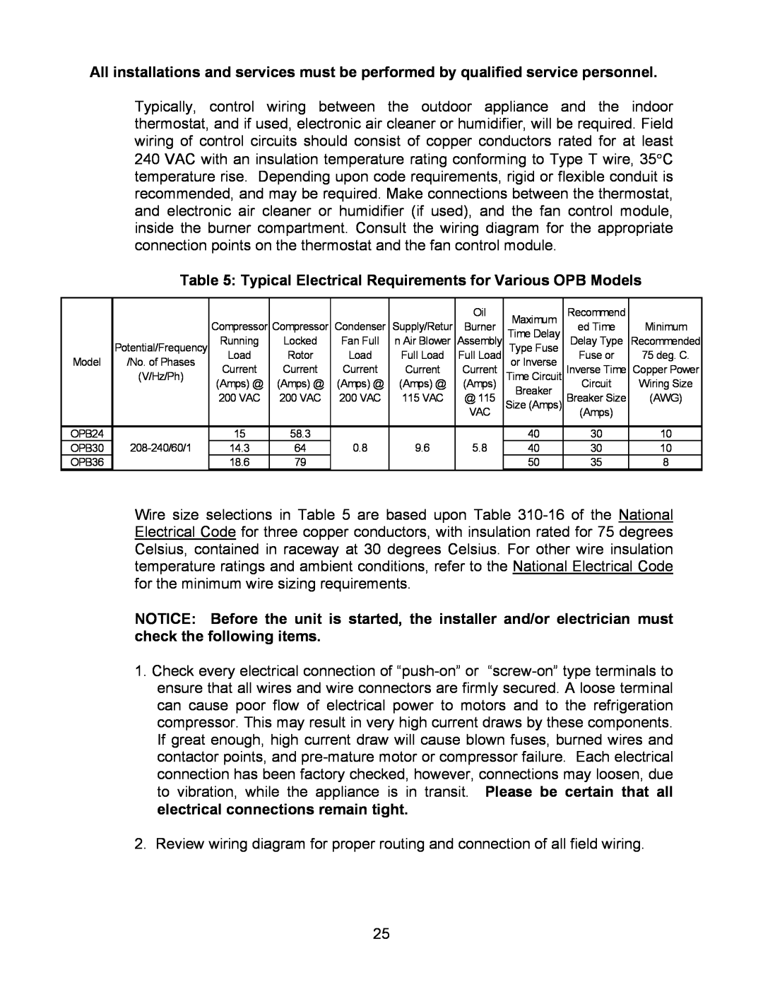
Table 5: Typical Electrical Requirements for Various OPB Models
|
| Compressor | Compressor | Condenser | Supply/Retur | Oil | Maximum | Recommend | Minimum |
|
| Burner | Time Delay | ed Time | |||||
| Potential/Frequency | Running | Locked | Fan Full | n Air Blower | Assembly | Type Fuse | Delay Type | Recommended |
Model | /No. of Phases | Load | Rotor | Load | Full Load | Full Load | or Inverse | Fuse or | 75 deg. C. |
| (V/Hz/Ph) | Current | Current | Current | Current | Current | Time Circuit | Inverse Time | Copper Power |
|
| (Amps) @ | (Amps) @ | (Amps) @ | (Amps) @ | (Amps) | Breaker | Circuit | Wiring Size |
|
| 200 VAC | 200 VAC | 200 VAC | 115 VAC | @ 115 | Breaker Size | (AWG) | |
|
| Size (Amps) | |||||||
|
|
|
|
|
| VAC |
| (Amps) |
|
|
|
|
|
|
|
|
|
|
|
OPB24 | 15 | 58.3 | 0.8 | 9.6 | 5.8 | 40 | 30 | 10 | |
OPB30 | 14.3 | 64 | 40 | 30 | 10 | ||||
OPB36 |
| 18.6 | 79 |
|
|
| 50 | 35 | 8 |
Wire size selections in Table 5 are based upon Table
NOTICE: Before the unit is started, the installer and/or electrician must check the following items.
1.Check every electrical connection of
2.Review wiring diagram for proper routing and connection of all field wiring.
25