All installations and services must be performed by qualified service personnel.
Therefore, choose a supply system static pressure drop of 0.2 in. W.G. (Then, the return air system will also have a static pressure drop of 0.2 in. W.G.) Furthermore, we will assume that the static pressure drops for all registers in the supply system will be 0.1 in. W.G.
This leaves a static pressure drop of only 0.1 in. W.G. for all the ducting between the outlet flange of the appliance to each of the registers. (We will assume that the pressure drop through any short piece of ductwork connecting a branch to a register is included in the 0.1 in. W.G. pressure drop of the register.) Now, the size of the ducting for each segment of the duct system can begin.
For the branch of the duct system, which includes segments “A”, “B”, “C”, “F”, and “H”, the pressure drop cannot exceed 0.1 in. W.G. This branch of the duct system has two
LeAH = LA + LB + LC + LF + LH
= (11 ft. + 6 ft.) + 11 ft. + 6 ft. + 22 ft. + 12 ft. + 3 ft.
=71 ft.
Using the flowrate, total length of the duct, and the pressure drop, the required size of the duct can be determined using the following equation.
⎡ | 1.82 | ⎤0.2058 |
D(in.) = ⎢ | 0.00123174 * Le( ft.)*V (CFM ) | ⎥ |
⎣ | ΔP(in. W.G.) | ⎦ |
**See page 75 for a copy of the ASHRAE chart.
This equation is applicable to standard air between 50 to 90 degrees F flowing through clean, round, galvanized ductwork with approximately 40 joints per 100 feet. Using duct lengths in feet, flowrate in CFM, and pressure drop in inches W.G., the equation will calculate the required circular duct diameter in inches. (If it is desired to substitute rectangular duct for circular duct, refer to Table 7 for equivalent sizes.)
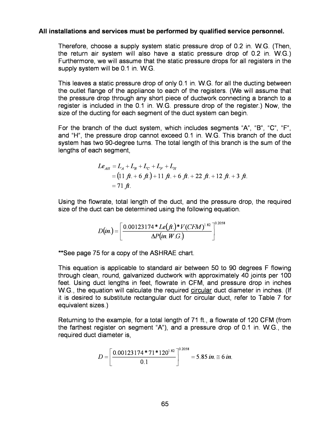
Returning to the example, for a total length of 71 ft., a flowrate of 120 CFM (from the farthest register on segment “A”), and a pressure drop of 0.1 in. W.G., the required duct diameter is,
⎡ | 1.82 | ⎤ | 0.2058 |
D = ⎢ | 0.00123174 * 71*120 | ⎥ | = 5.85 in. ≅ 6 in. |
⎣ | 0.1 | ⎦ |
|
65