All installations and services must be performed by qualified service personnel.
6.Open the inspection cover on the upper mounting plate.
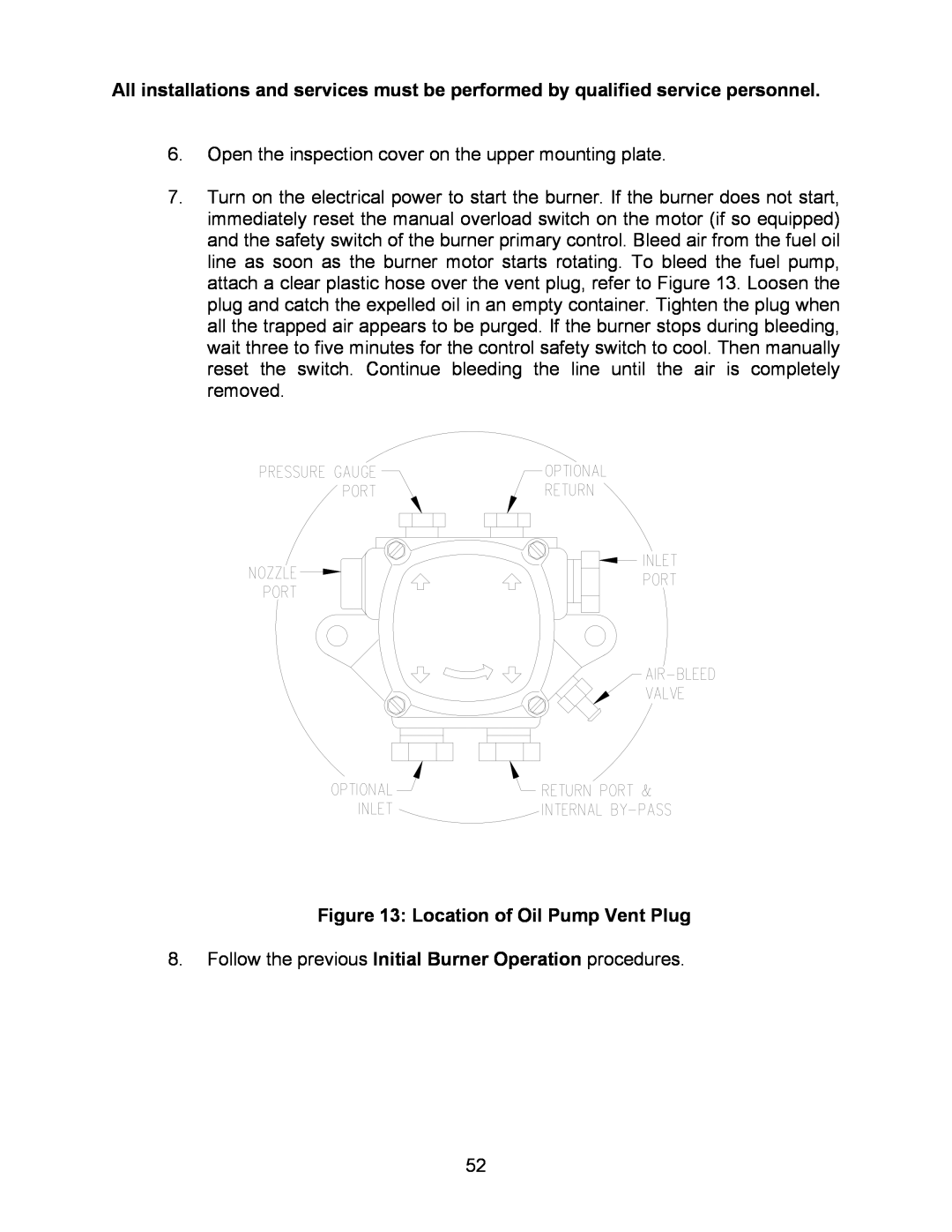
7.Turn on the electrical power to start the burner. If the burner does not start, immediately reset the manual overload switch on the motor (if so equipped) and the safety switch of the burner primary control. Bleed air from the fuel oil line as soon as the burner motor starts rotating. To bleed the fuel pump, attach a clear plastic hose over the vent plug, refer to Figure 13. Loosen the plug and catch the expelled oil in an empty container. Tighten the plug when all the trapped air appears to be purged. If the burner stops during bleeding, wait three to five minutes for the control safety switch to cool. Then manually reset the switch. Continue bleeding the line until the air is completely removed.
Figure 13: Location of Oil Pump Vent Plug
8.Follow the previous Initial Burner Operation procedures.
52
