All installations and services must be performed by qualified service personnel.
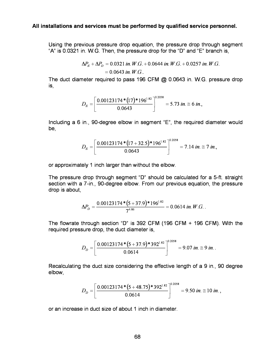
Using the previous pressure drop equation, the pressure drop through segment “A” is 0.0321 in. W.G. Then, the pressure drop for the “D” and “E” branch is,
ΔPE + ΔPD = 0.0321 in. W.G. + 0.0644 in. W.G. + 0.0257 in. W.G.
=0.0643 in. W.G..
The duct diameter required to pass 196 CFM @ 0.0643 in. W.G. pressure drop is,
| ⎡ | 1.82 | ⎤ | 0.2058 |
D | = ⎢ | 0.00123174 * (17)*196 | ⎥ | = 5.73 in. ≅ 6 in., |
| ||||
E | ⎣ | 0.0643 | ⎦ |
|
|
|
Including a 6 in.,
| ⎡ | 1.82 | ⎤ | 0.2058 |
D | = ⎢ | 0.00123174 * (17 + 32.5)*196 | ⎥ | = 7.14 in. ≅ 7 in., |
| ||||
E | ⎣ | 0.0643 | ⎦ |
|
|
|
or approximately 1 inch larger than without the elbow.
The pressure drop through segment “D” should be calculated for a
ΔPD = 0.00123174 * (5 + 37.9)*1961.82 = 0.0614 in. W.G. .
74.86
The flowrate through section “D” is 392 CFM (196 CFM + 196 CFM). With the required pressure drop, the duct diameter is,
| ⎡ | 1.82 | ⎤ | 0.2058 |
D | = ⎢ | 0.00123174 * (5 + 37.9)* 392 | ⎥ | = 9.07 in. ≅ 9 in. . |
| ||||
D | ⎣ | 0.0614 | ⎦ |
|
|
|
Recalculating the duct size considering the effective length of a 9 in., 90 degree elbow,
| ⎡ | 1.82 | ⎤ | 0.2058 |
D | = ⎢ | 0.00123174 * (5 + 48.75)* 392 | ⎥ | = 9.50 in. ≅ 10 in. , |
| ||||
D | ⎣ | 0.0614 | ⎦ |
|
|
|
or an increase in duct size of about 1 inch in diameter.
68
