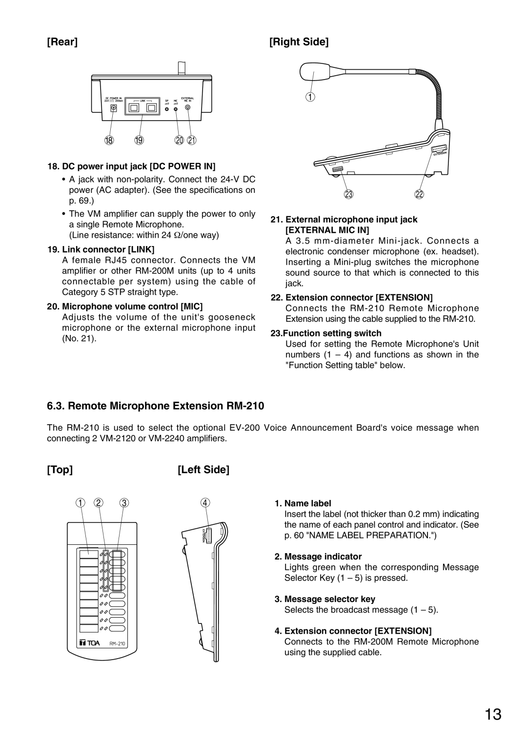
[Rear] | [Right Side] |
18 | 19 | 20 | 21 |
18.DC power input jack [DC POWER IN]
•A jack with
p.69.)
•The VM amplifier can supply the power to only
asingle Remote Microphone.
(Line resistance: within 24 Ω/one way)
19.Link connector [LINK]
A female RJ45 connector. Connects the VM amplifier or other
20.Microphone volume control [MIC]
Adjusts the volume of the unit's gooseneck microphone or the external microphone input (No. 21).
1
2322
21.External microphone input jack
[EXTERNAL MIC IN]
A 3.5
22.Extension connector [EXTENSION]
Connects the
23.Function setting switch
Used for setting the Remote Microphone's Unit numbers (1 – 4) and functions as shown in the "Function Setting table" below.
6.3. Remote Microphone Extension RM-210
The
[Top] |
|
| [Left Side] |
1 | 2 | 3 | 4 |
1.Name label
Insert the label (not thicker than 0.2 mm) indicating the name of each panel control and indicator. (See p. 60 "NAME LABEL PREPARATION.")
2.Message indicator
Lights green when the corresponding Message Selector Key (1 – 5) is pressed.
3.Message selector key
Selects the broadcast message (1 – 5).
4.Extension connector [EXTENSION]
Connects to the
13