17. RACK MOUNTING
Step 1. Remove 4 plastic feet from the unit's bottom side.
Step 2. Remove 2 screws on each side (located near the front).
Step 3. Fix the Rack Mounting Bracket
Note: Do not use the removed screws in the above step.
Step 4. Mount the unit on an equipment rack using the Bracket's accessory screws and fiber washers.
Note: When mounting the unit in an equipment rack not made by TOA, prepare separately the screws and washers appropriate for the rack.
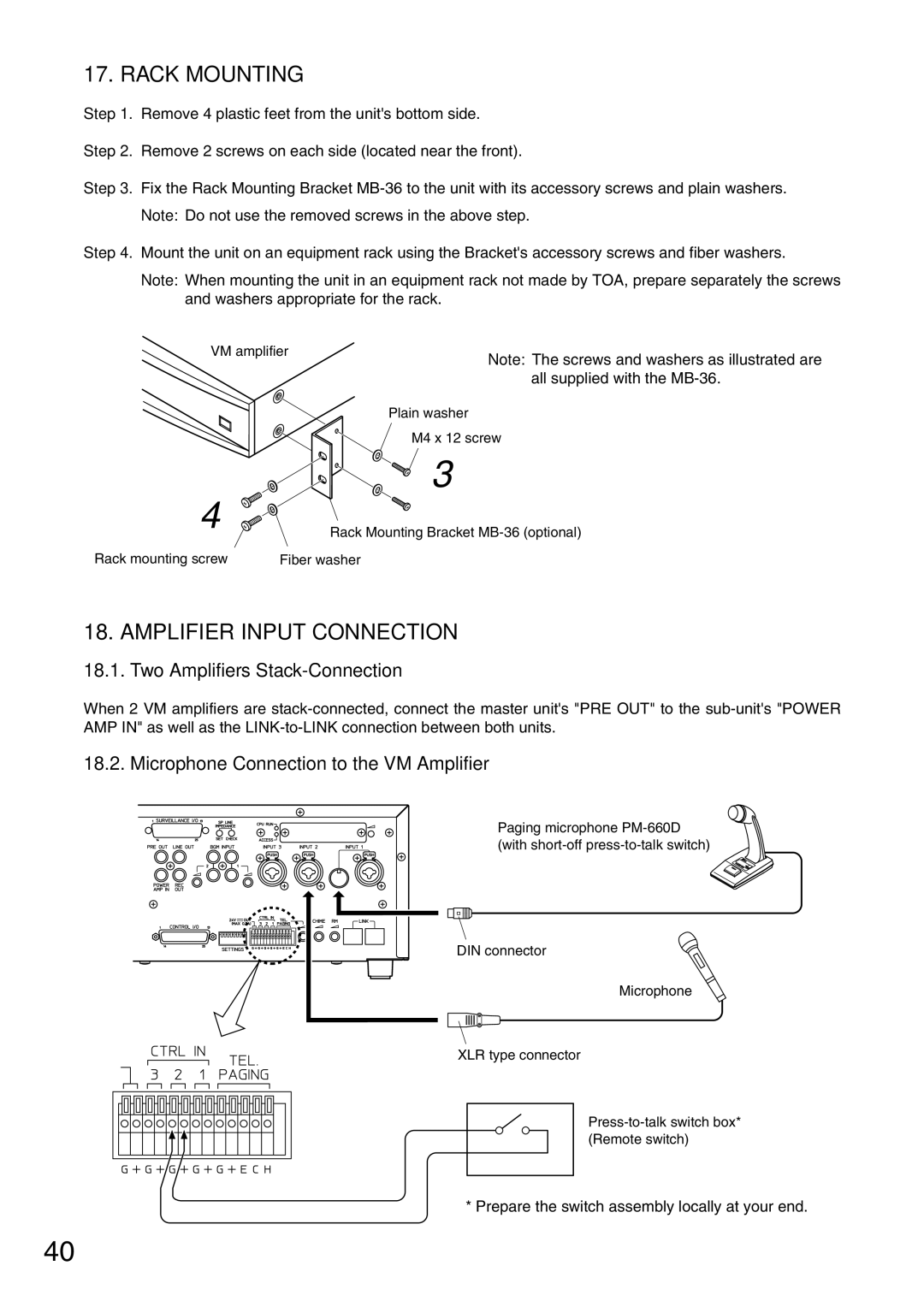
VM amplifier
Note: The screws and washers as illustrated are all supplied with the
4
Rack mounting screw
Plain washer
M4 x 12 screw
3
Rack Mounting Bracket
18. AMPLIFIER INPUT CONNECTION
18.1. Two Amplifiers Stack-Connection
When 2 VM amplifiers are
18.2. Microphone Connection to the VM Amplifier
Paging microphone
DIN connector
Microphone
XLR type connector
* Prepare the switch assembly locally at your end.
40