Step 3. Solder the input transformer to the removed input transformer board (5 places). Note: Be sure not to mistake the solder side for the mounting side.
Step 4. Cut off jumper wires (2 places marked with X for each input).
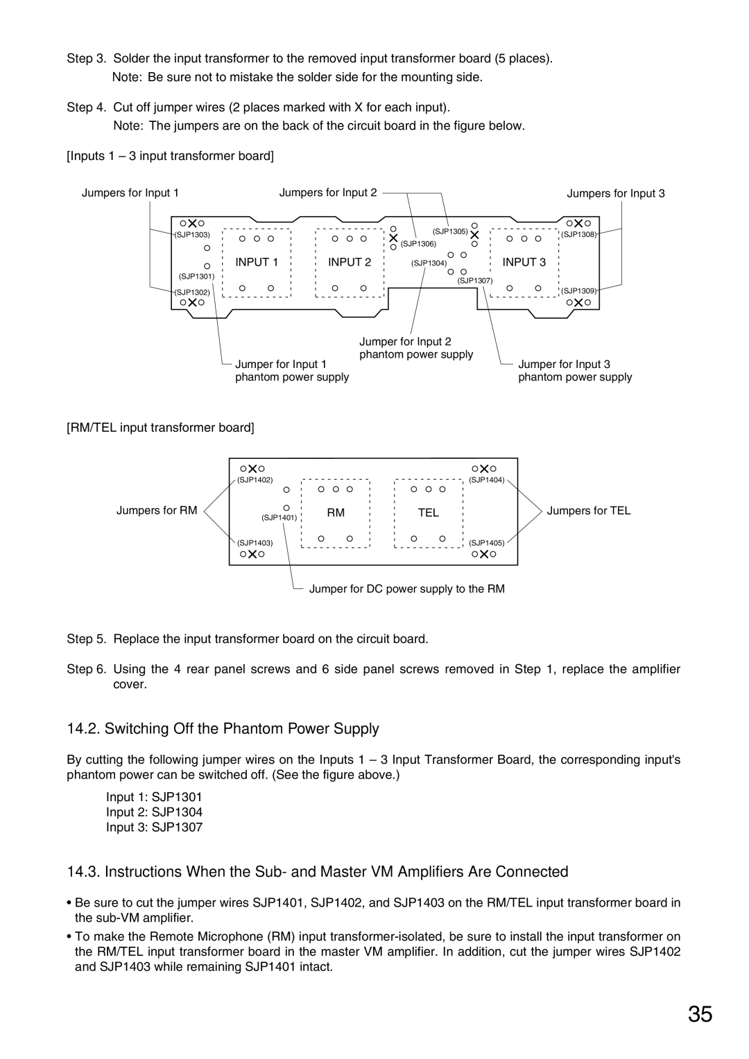
Note: The jumpers are on the back of the circuit board in the figure below.
[Inputs 1 – 3 input transformer board]
Jumpers for Input 1 | Jumpers for Input 2 | Jumpers for Input 3 |
(SJP1303)
(SJP1301)
(SJP1302)
INPUT 1
INPUT 2
(SJP1305)
(SJP1306)
(SJP1304) | INPUT 3 |
(SJP1307)
(SJP1308)
(SJP1309)
| Jumper for Input 2 |
Jumper for Input 1 | phantom power supply |
Jumper for Input 3 | |
phantom power supply | phantom power supply |
[RM/TEL input transformer board]
(SJP1402)
Jumpers for RM
(SJP1401)
(SJP1403)
RM
TEL
(SJP1404)
Jumpers for TEL
(SJP1405)
Jumper for DC power supply to the RM
Step 5. Replace the input transformer board on the circuit board.
Step 6. Using the 4 rear panel screws and 6 side panel screws removed in Step 1, replace the amplifier cover.
14.2. Switching Off the Phantom Power Supply
By cutting the following jumper wires on the Inputs 1 – 3 Input Transformer Board, the corresponding input's phantom power can be switched off. (See the figure above.)
Input 1: SJP1301
Input 2: SJP1304
Input 3: SJP1307
14.3. Instructions When the Sub- and Master VM Amplifiers Are Connected
•Be sure to cut the jumper wires SJP1401, SJP1402, and SJP1403 on the RM/TEL input transformer board in the
•To make the Remote Microphone (RM) input
35