Connected unit No. table (SW3)
| Switch No. |
| No. of Connected Units* | ||
6 |
| 7 |
| 8 | |
|
|
| |||
|
|
|
|
|
|
OFF |
| OFF |
| OFF | 0 |
|
|
|
|
|
|
ON |
| OFF |
| OFF | 1 |
OFF |
| ON |
| OFF | 2 |
|
|
|
|
|
|
ON |
| ON |
| OFF | 3 |
|
|
|
|
|
|
OFF |
| OFF |
| ON | 4 |
ON |
| OFF |
| ON | 5 |
*The total number of one
SW4 switch setting (Both switches are
Switch No. | BGM broadcast volume attenuation* | ||
1 | 2 | ||
| |||
|
|
| |
OFF | OFF | No attenuation | |
ON | |||
| |||
ON | Don't care | – ∞ dB (inaudible) | |
*Determines the attenuation level when the broadcast of higher priority (level 2 or 3) overrides the BGM broadcast (priority level 4). (See p.27
23.3. Remote Microphone's Function Switches
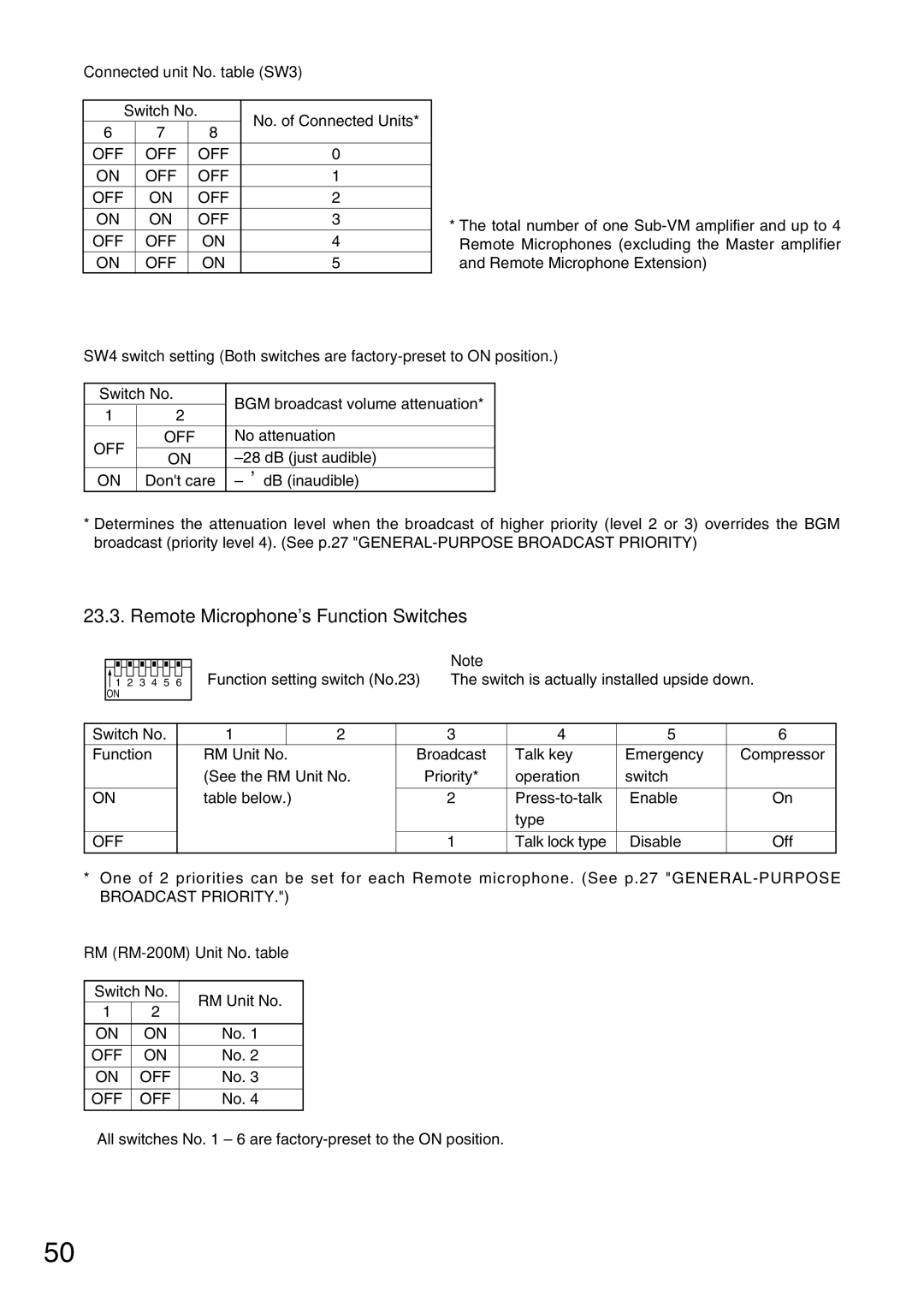
1 2 3 4 5 6 ON
Note
Function setting switch (No.23) The switch is actually installed upside down.
Switch No. | 1 |
| 2 | 3 | 4 | 5 | 6 |
Function | RM Unit No. |
|
| Broadcast | Talk key | Emergency | Compressor |
| (See the RM Unit No. | Priority* | operation | switch |
| ||
|
|
|
|
|
|
|
|
ON | table below.) |
| 2 | Enable | On | ||
|
|
|
|
| type |
|
|
|
|
|
|
|
|
|
|
OFF |
|
|
| 1 | Talk lock type | Disable | Off |
|
|
|
|
|
|
|
|
*One of 2 priorities can be set for each Remote microphone. (See p.27
RM (RM-200M) Unit No. table
Switch No. | RM Unit No. | ||
1 | 2 | ||
| |||
|
|
| |
ON | ON | No. 1 | |
|
|
| |
OFF | ON | No. 2 | |
|
|
| |
ON | OFF | No. 3 | |
|
|
| |
OFF | OFF | No. 4 | |
|
|
| |
All switches No. 1 – 6 are
50