21. CONTROL I/O CONNECTOR FUNCTIONS
The rear
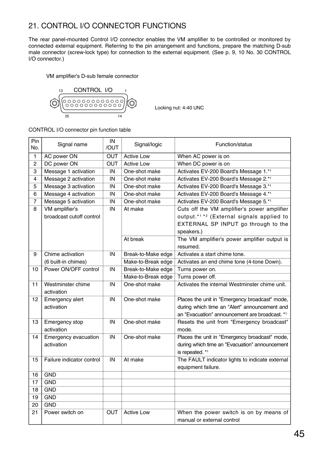
VM amplifier's
13 CONTROL I/O 1
Locking nut:
| 25 | 14 |
|
| |
CONTROL I/O connector pin function table |
| ||||
|
|
|
|
|
|
Pin | Signal name | IN |
| Signal/logic | Function/status |
No. | /OUT |
| |||
|
|
|
| ||
|
|
|
|
|
|
1 | AC power ON | OUT |
| Active Low | When AC power is on |
|
|
|
|
|
|
2 | DC power ON | OUT |
| Active Low | When DC power is on |
|
|
|
|
|
|
3 | Message 1 activation | IN |
| Activates | |
4 | Message 2 activation | IN |
| Activates | |
5 | Message 3 activation | IN |
| Activates | |
6 | Message 4 activation | IN |
| Activates | |
7 | Message 5 activation | IN |
| Activates | |
8 | VM amplifier's | IN |
| At make | Cuts off the VM amplifier's power amplifier |
| broadcast cutoff control |
|
|
| output.*1 *2 (External signals applied to |
|
|
|
|
| EXTERNAL SP INPUT go through to the |
|
|
|
|
| speakers.) |
|
|
|
|
|
|
|
|
|
| At break | The VM amplifier's power amplifier output is |
|
|
|
|
| resumed. |
|
|
|
|
|
|
9 | Chime activation | IN |
| Activates a start chime tone. | |
|
|
|
|
|
|
| (6 |
|
| Activates an end chime tone | |
|
|
|
|
|
|
10 | Power ON/OFF control | IN |
| Turns power on. | |
|
|
|
|
|
|
|
|
|
| Turns power off. | |
|
|
|
|
|
|
11 | Westminster chime | IN |
| Activates the internal Westminster chime unit. | |
| activation |
|
|
|
|
|
|
|
|
|
|
12 | Emergency alert | IN |
| Places the unit in "Emergency broadcast" mode, | |
| activation |
|
|
| during which time an "Alert" announcement and |
|
|
|
|
| an "Evacuation" announcement are broadcast. *1 |
13 | Emergency stop | IN |
| Resets the unit from "Emergency broadcast" | |
| activation |
|
|
| mode. |
|
|
|
|
|
|
14 | Emergency evacuation | IN |
| Places the unit in "Emergency broadcast" mode, | |
| activation |
|
|
| during which time an "Evacuation" announcement |
|
|
|
|
| is repeated. *1 |
15 | Failure indicator control | IN |
| At make | The FAULT indicator lights to indicate external |
|
|
|
|
| equipment failure. |
|
|
|
|
|
|
16 | GND |
|
|
|
|
|
|
|
|
|
|
17 | GND |
|
|
|
|
|
|
|
|
|
|
18 | GND |
|
|
|
|
|
|
|
|
|
|
19 | GND |
|
|
|
|
|
|
|
|
|
|
20 | GND |
|
|
|
|
|
|
|
|
|
|
21 | Power switch on | OUT |
| Active Low | When the power switch is on by means of |
|
|
|
|
| manual or external control |
|
|
|
|
|
|
45