2. PRINTER SETUP
ENGLISH VERSION
2.12 Position and Print Tone Fine Adjustment
2.12Position and Print Tone Fine Adjustment
<3>ADJUST SET
[PAUSE]
<3>ADJUST SET FEED ADJ.+10.0mm
[PAUSE]
<3>ADJUST SET CUT ADJ. +10.0mm
[PAUSE]
<3>ADJUST SET BACK ADJ. +5.0mm
[PAUSE]
<3>ADJUST SET
X ADJUST +50.0mm
[PAUSE]
<3>ADJUST SET TONE ADJ.<T> +3
[PAUSE]
<3>ADJUST SET TONE ADJ.<D>
[PAUSE]
<3>ADJUST SET RBN ADJ <FW>
[PAUSE]
<3>ADJUST SET RBN ADJ <BK>
[PAUSE]
<3>ADJUST SET THRESHOLD<R>1.0V
[PAUSE]
<3>ADJUST SET THRESHOLD<T>1.4V
[PAUSE]
This section describes how to fine adjust a print start position, cut/strip position, reverse feed amount, print tone, and ribbon motor torque.
When a fine adjustment is required, such as print start position, print tone, etc, follow the procedure below.
1.Turn on the printer and confirm that “ONLINE” appears on the LCD Message Display.
2.Press the [PAUSE] key to pause the printer.
3.Hold down the [RESTART] key for three seconds until “<1>RESET” is displayed.
4.Press the [FEED] or [RESTART] key until “<3>ADJUST SET” appears on the LCD Message Display.
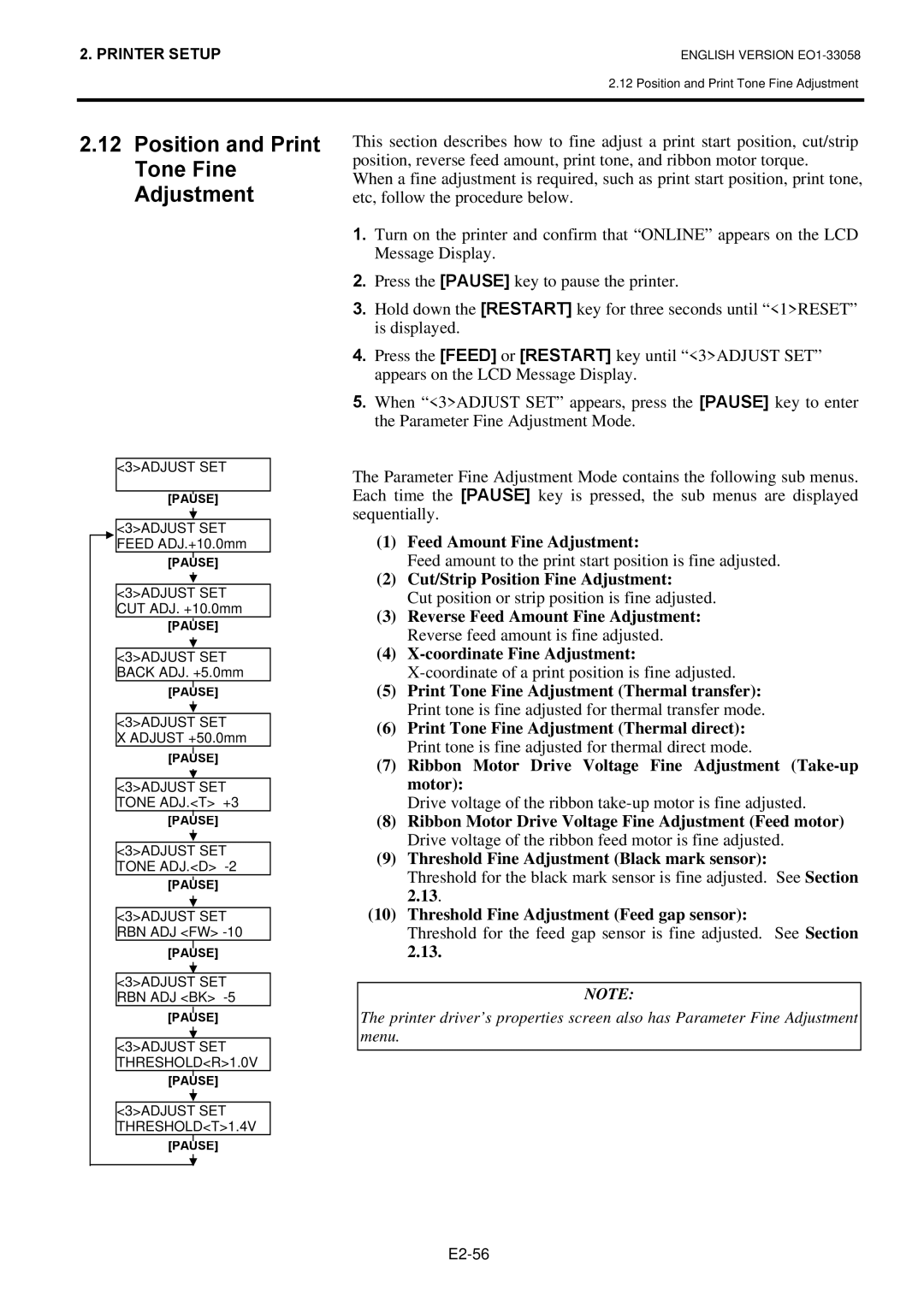
5.When “<3>ADJUST SET” appears, press the [PAUSE] key to enter the Parameter Fine Adjustment Mode.
The Parameter Fine Adjustment Mode contains the following sub menus. Each time the [PAUSE] key is pressed, the sub menus are displayed sequentially.
(1)Feed Amount Fine Adjustment:
Feed amount to the print start position is fine adjusted.
(2)Cut/Strip Position Fine Adjustment:
Cut position or strip position is fine adjusted.
(3)Reverse Feed Amount Fine Adjustment: Reverse feed amount is fine adjusted.
(4)X-coordinate Fine Adjustment:
(5)Print Tone Fine Adjustment (Thermal transfer): Print tone is fine adjusted for thermal transfer mode.
(6)Print Tone Fine Adjustment (Thermal direct): Print tone is fine adjusted for thermal direct mode.
(7)Ribbon Motor Drive Voltage Fine Adjustment
Drive voltage of the ribbon
(8)Ribbon Motor Drive Voltage Fine Adjustment (Feed motor) Drive voltage of the ribbon feed motor is fine adjusted.
(9)Threshold Fine Adjustment (Black mark sensor):
Threshold for the black mark sensor is fine adjusted. See Section 2.13.
(10)Threshold Fine Adjustment (Feed gap sensor):
Threshold for the feed gap sensor is fine adjusted. See Section 2.13.
NOTE:
The printer driver’s properties screen also has Parameter Fine Adjustment menu.