SX4T Series
Vorsicht
CE Compliance for EU only
SX4T Series
Waste Recycling information for users
For all countries and areas
Meanings of Each Symbol
Safety Summary
Request Regarding Maintenance
Precautions
Table of Contents
EA2-1
EA1-1
EA3-1
EA4-1
Product Overview
Introduction Features Unpacking
No FM1647000
Accessories
Doc. No. EO2-33021
Quality Control Report 1 sheet
Front View
Dimensions
Rear View
Following chapters
Interior
Operation Panel
Option Name Type Description
Options
Setup Flow
Printer Setup
Procedure
Reference
Installation
Fitting the Fan Filter
Connecting the Power Cord
Example of US Type
Loading the Media
Do not over-tighten the Locking Ring of the Supply Holder
Setting the Black Mark Sensor position
Setting the Feed Gap Sensor position
Remove the Locking Screw that secures the Media Sensor
Strip mode Option
Batch mode
STANDARD/PEEL OFF position
Cut mode Option
Built-in rewinder mode Option
Loading the Ribbon
Auto Ribbon Saving Mode
Connecting the Cables to Your Printer
Turning on the Printer
Turning the Printer
Pcmcia Cards
Paragraphs outline how to insert Pcmcia cards
Following Pcmcia cards or equivalent can be used
How to enter the System Mode
While 2PARAMETER SET is displayed on the LCD Message
Parameter Setting
Time the Pause key is pressed, the sub menus are displayed
Sequentially
Use the Feed or Restart key to select a desired option
Character Code Selection
After selecting a character code, press the Pause key
Character Zero Selection
After selecting a baud rate, press the Pause key
Baud Rate Selection
Data Length Selection
After selecting a data length, press the Pause key
Parity Selection
Stop Bit Selection
Flow Control Code Selection
After selecting a language, press the Pause key
LCD Language Selection
Auto Forward Wait Selection
After selecting an auto forward wait, press the Pause key
Feed key
Head Up Cut/Rewinder Selection
After selecting the solenoid type, press the Pause key
Solenoid Type Selection
Ribbon Saving Function Selection
Control Code Selection
After selecting the Strip Wait Status, press the Pause key
Strip Wait Status Selection
Feed Key Function Selection
After selecting the Feed key function, press the Pause key
After selecting a Kanji code, press the Pause key
Kanji Code Selection
Euro Code Selection
After selecting a Euro code, press the Pause key
After selecting auto print head check, press the Pause key
Auto Print Head Check Selection
Centronics Interface ACK/BUSY Timing Selection
After selecting an ACK/BUSY timing, press the Pause key
Input Prime Selection
Web Printer Function Selection
After selecting the Input Prime, press the Pause key
Expansion I/O Interface Type Selection
Ribbon Near End Selection
Plug & Play Selection
Centronics Interface Selection
After selecting a Plug & Play, press the Pause key
Pre-Strip Selection
Label End/Ribbon End Selection
After selecting the Pre-strip function, press the Pause key
Reverse Feed Speed Selection
Maxi Code Specification Selection
After selecting the Back Feed Speed, press the Pause key
Print Head Type Selection
System Mode Password Setting
After selecting a print head type, press the Pause key
After selecting the receive buffer, press the Pause key
Dump Mode Setting
Use the Feed or Restart key to select a printing method
After selecting a printing method, press the Pause key
Receive Buffer Size
Data in the receive buffer is printed as follows
Required Label Length
When the Pause key is pressed, Basic program is executed
Introduction
Installing the Printer Drivers
General Description
Parallel Interface
Installing the Printer Driver
Windows 98/Me
E2-38
Windows 2000/XP
E2-40
USB Interface
E2-42
E2-43
E2-44
Finish button
E2-46
E2-47
E2-48
Uninstalling the Printer Driver
Adding a LAN Port Windows 98/ME
Adding/Deleting a LAN Port
Deleting a LAN Port
Others
Printer Driver Upgrades
Using the Printer Driver
Print Test
Adjustment
When using a Strip Module or an optional Cutter Module
Feed Amount Fine Adjustment
Position and Print Tone Fine Adjustment
Cut/Strip Position Fine Adjustment
Coordinate Fine Adjustment
Position and Print
When setting +0.0 mm
Tone Fine
Example of Cut Position Fine Adjustment
Example of Strip Position Fine Adjustment
Restart Feed
When setting +50.0 mm
When setting -50.0 mm
Position and Print Tone Fine Adjustment
Ribbon Motor Voltage Fine Adjustment
Jam errors
Threshold Setting
Select the sensor to be adjusted by using the Feed key
Manually set
Feed and Pause keys
„ When using the Feed Gap Sensor
„ When using the Black Mark Sensor
„ Storing a No Media Level Voltage
„ Manual Threshold Setting
Press and hold the Restart or Feed key for about 3 seconds
THRESHOLDR4.0V THRESHOLDT4.0V THRESHOLDR3.9V
Operation Panel
On Line Mode
Operation
Reset
Press and hold the Restart key for 3 seconds or longer
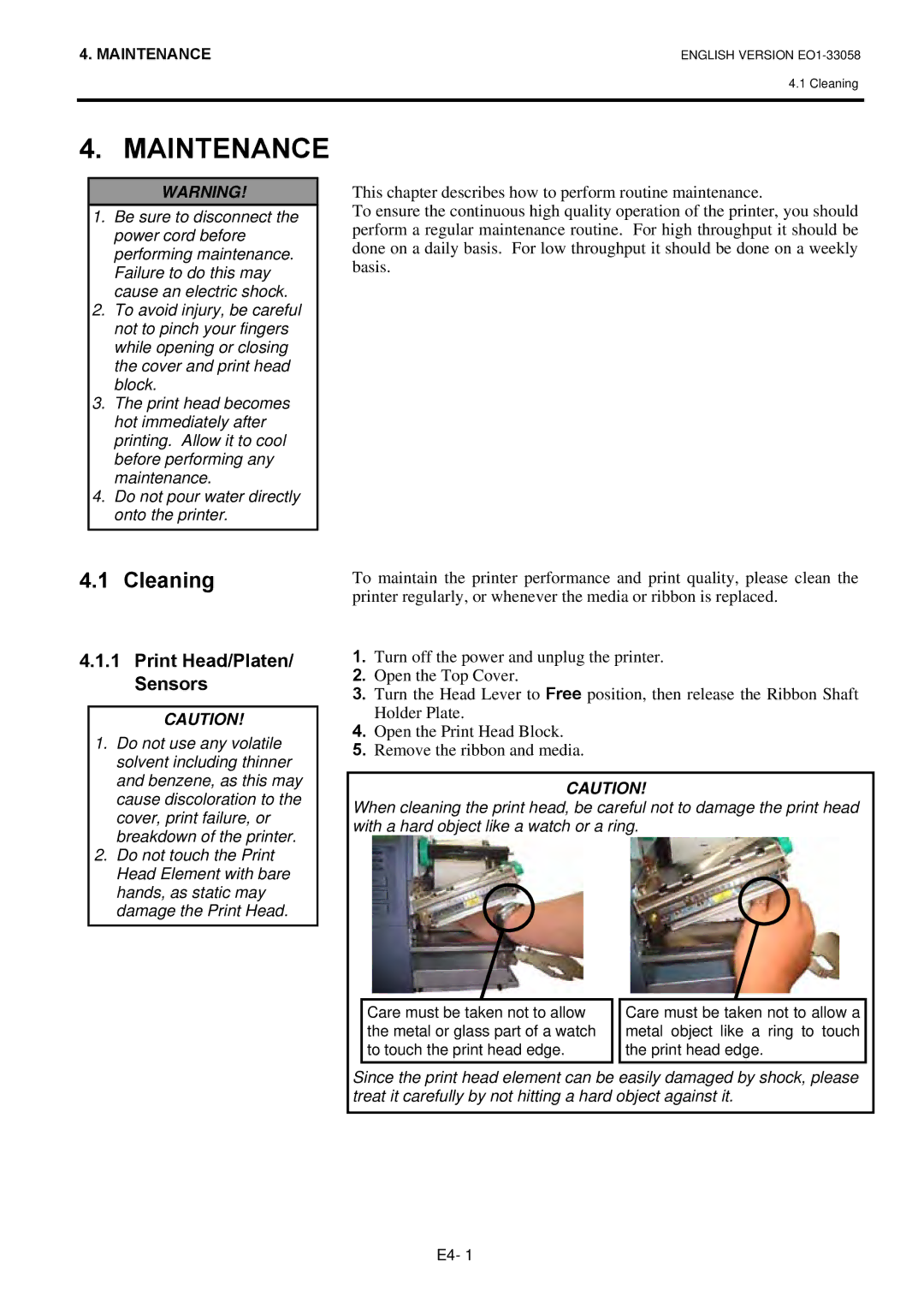
Cleaning
Maintenance
Print Head/Platen/ Sensors
Covers and Panels
Optional Cutter Module
Error Messages
Troubleshooting
Error Messages Problems/Causes Solutions
Restart key
Media has run out Load new media. Then press
Error Messages Problems/Cause Solutions
Media is slack Take up any slack in the media
Ribbon has run out Load a new ribbon. Then press
Possible Problems Causes Solutions
Possible Problems
Ribbon is not loaded properly Load the ribbon properly
Refer to .1 Media
Cutter blade is dirty Clean the cutter blade
⇒Section
Removing Jammed Media
This section describes the printer specifications
Printer Specifications
Model
SX4T-GS20-QM-R
Media
Supply Specifications
Media Type
Label
Label
Detection Area of the Transmissive Sensor
Tag paper with square holes
Effective Print Area
Detection Area of the Reflective Sensor
„ B-9704-RFID-U1-US-R and B-9704-RFID-U1-EU-R
Rfid Tags
„ B-9704-RFID-H1-QM-R
Media feed direction
Recommended Media and Ribbon Types
Ribbon
Media type Description
Ribbon type Description
Care/Handling of Media and Ribbon
Combination of Media and Ribbon
Media type Vellum paper and label
Appendix 1 Messages and Leds
Symbols in the message
Wrong password was entered
Printer is waiting for a password to Be entered
Base LAN Board is being
Initialized Printer did not succeed in writing
Following message appears
Parallel interface Centronics Standard
Appendix 2 Interface
PIN
Connector
Serial interface Standard
LAN cable
Physical Layer
100BASE-TX UTP category
Cable length Segment length Max m
Expansion I/O Interface Option B-7704-IO- QM-R
RFID-U1-EU
RFID-U1-US
RFID-H1-QM
SX704-RFID-U2-US-R
When purchasing the power cord
Appendix 3 Power Cord
At least, 125% of the rated current of the product
Appendix 4 Print Samples
JAN13, EAN13
Interleaved 2
EAN13+2 digits
EAN13+5 digits
Industrial 2
UPC-A+5 digits
Customer bar code
KIX Code
Appendix 5 Glossaries
Device used to remove labels from the backing paper
See Black mark sensor
Media and ribbon
See Feed gap sensor
3-1, A1-1
Index
Index
Waste Recycling information for users
EO1-33058E