2.PRINTER SETUP
ENGLISH VERSION
2.13 Threshold Setting
2.13Threshold Setting (Cont.)
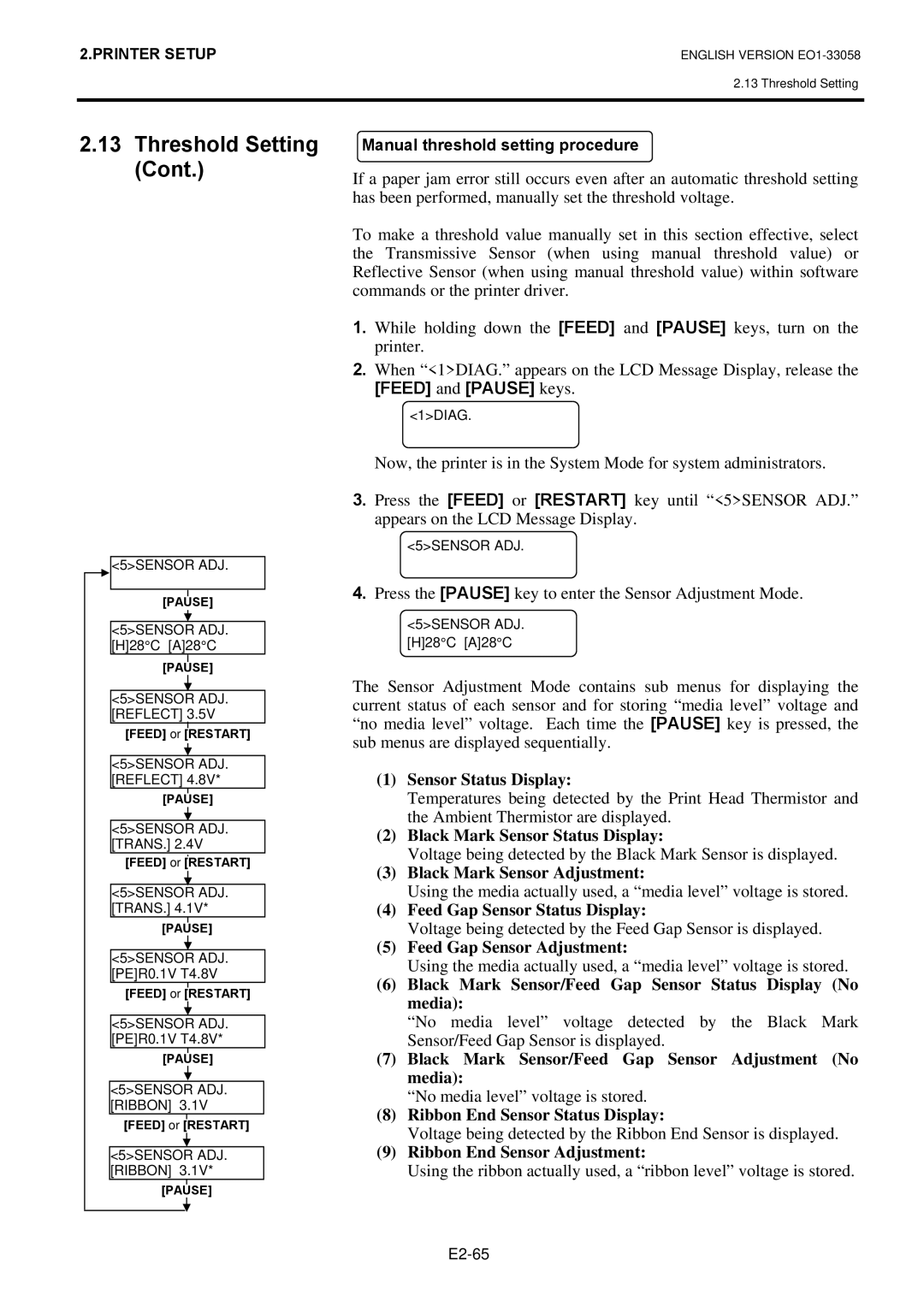
<5>SENSOR ADJ.
[PAUSE]
<5>SENSOR ADJ. [H]28°C [A]28°C
[PAUSE]
<5>SENSOR ADJ. [REFLECT] 3.5V
[FEED] or [RESTART]
<5>SENSOR ADJ. [REFLECT] 4.8V*
[PAUSE]
<5>SENSOR ADJ. [TRANS.] 2.4V
[FEED] or [RESTART]
<5>SENSOR ADJ. [TRANS.] 4.1V*
[PAUSE]
<5>SENSOR ADJ. [PE]R0.1V T4.8V
[FEED] or [RESTART]
<5>SENSOR ADJ. [PE]R0.1V T4.8V*
[PAUSE]
<5>SENSOR ADJ. [RIBBON] 3.1V
[FEED] or [RESTART]
<5>SENSOR ADJ. [RIBBON] 3.1V*
[PAUSE]
Manual threshold setting procedure
If a paper jam error still occurs even after an automatic threshold setting has been performed, manually set the threshold voltage.
To make a threshold value manually set in this section effective, select the Transmissive Sensor (when using manual threshold value) or Reflective Sensor (when using manual threshold value) within software commands or the printer driver.
1.While holding down the [FEED] and [PAUSE] keys, turn on the printer.
2.When “<1>DIAG.” appears on the LCD Message Display, release the
[FEED] and [PAUSE] keys.
<1>DIAG.
Now, the printer is in the System Mode for system administrators.
3.Press the [FEED] or [RESTART] key until “<5>SENSOR ADJ.” appears on the LCD Message Display.
<5>SENSOR ADJ.
4.Press the [PAUSE] key to enter the Sensor Adjustment Mode.
<5>SENSOR ADJ. [H]28°C [A]28°C
The Sensor Adjustment Mode contains sub menus for displaying the current status of each sensor and for storing “media level” voltage and “no media level” voltage. Each time the [PAUSE] key is pressed, the sub menus are displayed sequentially.
(1)Sensor Status Display:
Temperatures being detected by the Print Head Thermistor and the Ambient Thermistor are displayed.
(2)Black Mark Sensor Status Display:
Voltage being detected by the Black Mark Sensor is displayed.
(3)Black Mark Sensor Adjustment:
Using the media actually used, a “media level” voltage is stored.
(4)Feed Gap Sensor Status Display:
Voltage being detected by the Feed Gap Sensor is displayed.
(5)Feed Gap Sensor Adjustment:
Using the media actually used, a “media level” voltage is stored.
(6)Black Mark Sensor/Feed Gap Sensor Status Display (No media):
“No media level” voltage detected by the Black Mark Sensor/Feed Gap Sensor is displayed.
(7)Black Mark Sensor/Feed Gap Sensor Adjustment (No media):
“No media level” voltage is stored.
(8)Ribbon End Sensor Status Display:
Voltage being detected by the Ribbon End Sensor is displayed.
(9)Ribbon End Sensor Adjustment:
Using the ribbon actually used, a “ribbon level” voltage is stored.