4 Replacement Procedures | 4.9 ODD Bay Module |
Disassembling the ODD Drive
NOTE: Do not disassemble the ODD drive when it is working normally. Disassemble or replace the ODD drive only if it fails.
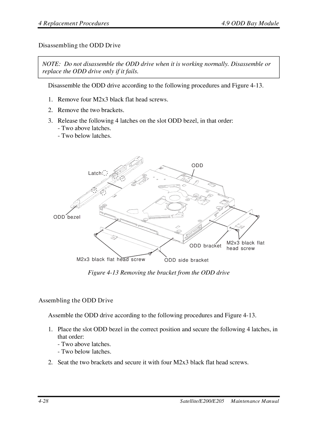
Disassemble the ODD drive according to the following procedures and Figure
1.Remove four M2x3 black flat head screws.
2.Remove the two brackets.
3.Release the following 4 latches on the slot ODD bezel, in that order:
-Two above latches.
-Two below latches.
ODD
Latch
ODD bezel
M2x3 black flat
ODD bracket head screw
M2x3 black flat head screw | ODD side bracket |
Figure 4-13 Removing the bracket from the ODD drive
Assembling the ODD Drive
Assemble the ODD drive according to the following procedures and Figure
1.Place the slot ODD bezel in the correct position and secure the following 4 latches, in that order:
-Two above latches.
-Two below latches.
2.Seat the two brackets and secure it with four M2x3 black flat head screws.
Satellite/E200/E205 Maintenance Manual |