Manuals
/
Toshiba
/
Computer Equipment
/
Personal Computer
Toshiba
E205
manual
System Board Back View, Appendices Apx. B Board Layout
Models:
E205
1
208
243
243
Download
243 pages
37.96 Kb
205
206
207
208
209
210
211
212
Troubleshooting
Install
Error codes
Computer Block Diagram
Bluetooth
Password
Error! Bookmark not
Symbol examples
Wireless LAN Card
System Board Configurations
Page 208
Image 208
Appendices
Apx. B Board Layout
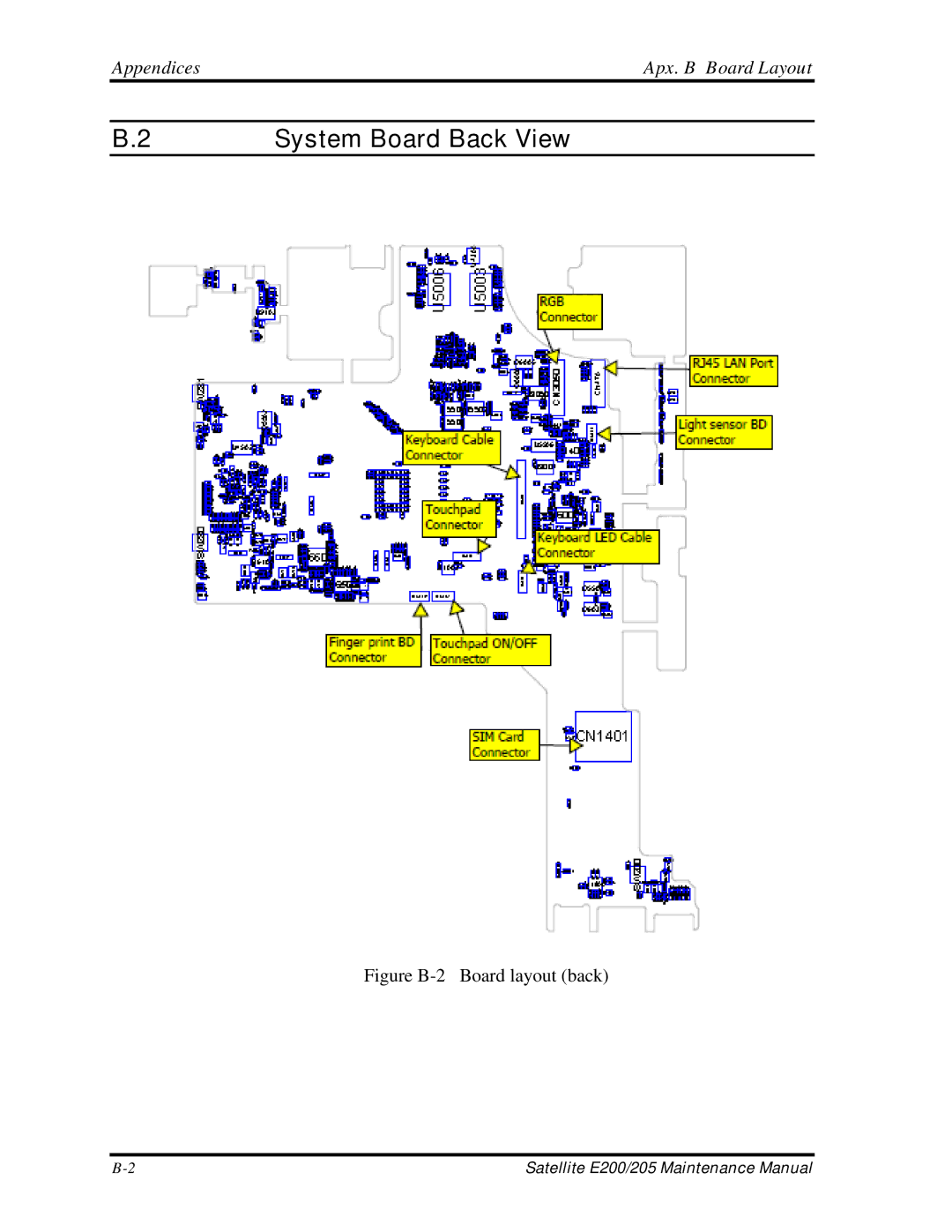
B.2
System Board Back View
Figure
B-2
Board layout (back)
B-2
Satellite E200/205 Maintenance Manual
Page 207
Page 209
Page 208
Image 208
Page 207
Page 209
Contents
PSE20 PSE25
Disclaimer
Copyright
Trademarks
Safety Precautions
Preface
Satellite/E200/E205 Maintenance Manual
Conventions
Acronyms
Table of Contents
Error! Bookmark not
Defined
Chapter Diagnostic Programs
Chapter
Error
Bookmark not defined
CPU
Installing the Speakers
Appendices
Hardware Overview
Hardware Overview
Chapter Contents
Figures
Tables
Features
Features Hardware Overview
Hardware Overview Features
ODD
Features Hardware Overview
Hardware Overview Features
ID Parts Description Placement
Computer Block Diagram
System Board Configurations
System Unit Components
Hardware Overview System Unit Components
System Unit Components Hardware Overview
− Gpio
KBC
Hardware Overview System Unit Components
2.5-inch HDD
2.5-inch HDD Hardware Overview
DVD Super Multi +-R Double Layer
Hardware Overview DVD Super Multi +-R Double Layer
Power Supply
Power Supply Hardware Overview
Main Battery
Battery Charging Control
Batteries
Hardware Overview Batteries
RTC Battery
Batteries Hardware Overview Quick/Normal Charging Time
Chapter Troubleshooting
Troubleshooting
Chapter Contents
Procedure
HDD Error Code and Status
Outline Troubleshooting
Outline
Basic Flowchart
Troubleshooting Basic Flowchart
Basic Flowchart Troubleshooting
Basic Flowchart 1/2
END
Basic Flowchart Troubleshooting
Troubleshooting Power Supply
Procedure 1 Power Icon Check
Power Supply Troubleshooting
DC in LED
Procedure 2 Connection Check
Procedure 3 Replacement Check
Procedure 1 Message Check
System Board Troubleshooting
System Board
Troubleshooting System Board
Procedure 2 Test Program Check
Procedure 2 Partition Check
HDD Troubleshooting
HDD
Troubleshooting HDD
Procedure 3 Format Check
Procedure 4 Test Program Check
HDD Error Code and Status
Procedure 5 Connector Check and Replacement Check
Keyboard Troubleshooting
Procedure 1 Test Program Check
Procedure 2 Connector Check and Replacement Check
Keyboard
Troubleshooting Display
Procedure 1 External Monitor Check
Procedure 3 Connector Check and Replacement Check
Display
Display Troubleshooting
Procedure 1 ODD Cleaning Check
ODD Optical Disk Drive
10 LAN Troubleshooting
LAN
Procedure 2 Connector Check
Finger Print Optional2.10 Audio Test Troubleshooting
Finger Print Optional
Troubleshooting Finger Print
Audio Test
Ieee 1394 Test Troubleshooting
Ieee 1394 Test
Troubleshooting Cooling Module
Cooling Module
Cooling Module Troubleshooting
Diagnostic Programs
Diagnostic Programs
Iii
Page
General Diagnostic Programs
General
Diagnostic Programs General
Quick Start Diagnostic Programs
Quick Start
Quick Test
Customization Test
Diagnostic Programs Quick Start
CPU Speed Test Step by Step
Diagnostic Programs Quick Start
Keyboard Layout test
Hotkey Test
Audio Record Test
Audio Play Test
DMI Read
DMI Write
9 3D Sensor Test
If all data is less than ranges, it will be OK
Rear Upper
Right Upper
Front Upper
Left
System Information
View Logs
Diagnostics Screen Explanation
Diagnostics Windows
Exit to Free DOS
Test Running Status and Report Panel
Program Name and Its Version Service Diagnostic Ver1.10
Title Bar
Quick Start Diagnostic Programs
Diagnostic Programs 3Option
Options
Overview
Options Menu Notes
Option Diagnostic Programs
Batch Parameters Configuration
Wait On Error
Break On Error
Pause Enable
Monitor Battery Life
Item’s Parameters Configuration
∙ Time Limit Hrs
∙ Time Limit Min
∙ Number Of Loops
∙ Parameters
∙ Interactive
Load Batch Parameters
Save Batch Parameters
LOG Parameters Setting
Append to Old Log File
Log Device Info on Fail
∙ Log file Name
Specify LOG Viewer
∙ ↑, ↓
LOG Viewer
∙ Page Up, Page Down
LOG File Sample
Pass
Subtests Diagnostic Programs
Subtests
Diagnostic Programs Subtests
HDD
Vesamem
System Test
Diagnostic Programs System Test
Subtest 01 CPU
NPU Basic Functions Test
System Test Diagnostic Programs
NPU Interrupt Test
Subtest 02 Boards
Subtest 03 FAN Speed Test
Diagnostic Programs System Test
Memory Test Diagnostic Programs
Subtest 01 Bios ROM
Memory Test
Subtest 02 Parity
Diagnostic Programs Memory Test
Subtest 03 Patterns
Subtest 04 Extended Pattern
Diagnostic Programs Memory Test
Subtest 05 Walking 1’s Test
Subtest 06 Walking 0’s Test
Subtest 07 Memory Address
Subtest 08 Refresh Test
Subtest 11 Data Bus Test
Subtest 12 Memory Speed Test
Storage Diagnostic Programs
Password:hard disk
Storage
Subtest 01 HDD
Diagnostic Programs Storage
Storage Diagnostic Programs
Subtest 02 ODD
Video
Video Diagnostic Programs
Subtest
Diagnostic Programs Video
Video Diagnostic Programs
Subtest 02 640 * 480 VGA Mode
Subtest 03 Vesa Video Modes
Subtest 04 Vesa Video Memory
Subtest 05 AGP Test
Subtest 06 LCD Panel Test
Subtest 08 Color Purity Test
Subtest 09 Direct Color Test
Subtest 10 DAC/Palette Address
Subtest 01 LAN Card
Communication Comm
Subtest 1394
Peripheral
Diagnostic Programs Peripheral
Subtest Keyboard
Peripheral Diagnostic Programs
Subtest Led Test
Diagnostic Programs Peripheral
Peripheral Diagnostic Programs
Error Codes and description
Diagnostic Programs 11Error Codes and Description
Error Codes and Description Diagnostic Programs
03xx Board
FAN
31xx Audio
Can not find IEEE1394
Quick Test Item List3 Diagnostic Programs
Quick Test Item List
Chapter Replacement Procedures
Replacement Procedures
Chapter Contents
HDD
Error! Bookmark not
Figures
29 Removing the display mask
General Replacement Procedures
HDD
Replacement Procedures General
Safety Precautions
Satellite/E200/E205 Maintenance Manual
Before You Begin
Disassembly Procedures
Assembly Procedures
Tools and Equipment
Screw Tightening Torque
Symbol examples
Symbols of Screws on the Computer Body
Colors of Screw Shanks
Battery Pack/Bridge Media
Replacement Procedures Battery Pack/Bridge Media
Battery Pack
Removing the Battery Pack
Battery Pack/Bridge Media Replacement Procedures
Installing the Battery Pack
Bridge Media SD Card / Memory Stick / xDPicture Card
Removing the Bridge Media
Installing the Bridge Media
Replacement Procedures Keyboard
Removing Keyboard
Keyboard Replacement Procedures
Installing the Keyboard
Bottom Cover
Replacement Procedures Bottom Cover
Removing the Bottom Cover
Bottom Cover Replacement Procedures
Latch Bottom cover
Installing the Bottom Cover
Display Assembly Replacement Procedures
Display Assembly
Removing the Display Assembly
Replacement Procedures Display Assembly
Installing the Display Assembly
Memory Module
Memory Module Replacement Procedures
Removing the Memory Module
Replacement Procedures Memory Module
Installing the Memory Module
Wireless LAN Card Replacement Procedures
Wireless LAN Card
Removing the Wireless LAN Card
Replacement Procedures Wireless LAN Card
Installing the Wireless LAN Card
HDD Replacement Procedures
Removing the HDD
Replacement Procedures HDD
11 Removing the HDD chassis
Installing the HDD
ODD Bay Module
Replacement Procedures ODD Bay Module
Removing the ODD Bay Module
ODD Bay Module Replacement Procedures
Installing the ODD Bay Module
Disassembling the ODD Drive
Assembling the ODD Drive
Bluetooth Module Replacement Procedures
Bluetooth module
Removing the Bluetooth module
Replacement Procedures Bluetooth Module
Installing the Bluetooth Module
CPU Cooling Module and Fan
CPU Cooling Module and Fan Replacement Procedures
Remove the CPU cooling module and Fan
Replacement Procedures CPU Cooling Module and Fan
16 Applying silicon grease
Installing the CPU Cooling Module and Fan
12 CPU
Replacement Procedures 12 CPU
Removing the CPU
12 CPU Replacement Procedures
Installing the CPU
22 Securing the CPU
System Board Replacement Procedures
Removing the System Board
Replacement Procedures4.13 System Board
23 Disconnect from system board
Installing the System Board
Speakers
Replacement Procedures Speakers
Removing the Speakers
Speakers Replacement Procedures
Installing the Speakers
Switch Board and Finger Print Board
Removing Switch Board and Finger Print Board
Switch Board and Finger Print Board Replacement Procedures
Installing Switch Board and Finger Print Board
Light Sensor Board and Audio Board
Replacement Procedures Light Sensor Board and Audio Board
Removing the Light Sensor Board and Audio Board
Light Sensor Board and Audio Board Replacement Procedures
Installing the Power Board, Switch Board and Logo LED Board
DC-IN cable, RGB Board and RJ45 cable
Removing DC-IN cable, RGB Board and RJ45 cable
DC-IN cable, RGB Board and RJ45 cable Replacement Procedures
Installing DC-IN cable, RGB Board and RJ45 cable
Display Mask
Replacement Procedures Display Mask
Open Display Mask Removing the Display Mask
Display Mask Replacement Procedures
Installing the Display Mask
LCD Module
Replacement Procedures LCD Module
Open LCD module Removing the LCD module
LCD Module Replacement Procedures
31 Removing the LCD module
Installing the LCD Module
LCD Module CCD Board and MIC
CCD Board and MIC
Removing the CCD Board and MIC
Replacement Procedures CCD Board and MIC
Installing the CCD Board and MIC
LED Board and Card Reader Board
LED Board and Card Reader Board Replacement Procedures
Removing the LED Board and Card Reader Board
Replacement Procedures LED Board and Card Reader Board
Installing the LED Board and Card Reader Board
Appendices
CN200 Hot key Connector 6-Pin
CN3050 RGB Connector 14-Pin
Precautions for handling the LCD module
Apx. a Handling the LCD Module Appendices
Appendices Apx. a Handling the LCD Module
Apx. a Handling the LCD Module Appendices
Appendices Apx. a Handling the LCD Module
Apx. a Handling the LCD Module Appendices
Apx. B Board Layout Appendices
Figure B-1 Board layout front
System Board Back View
Appendices Apx. B Board Layout
Appendices Apx. C Pin Assignments
RGB BD Connector 14-Pin
CN200 Hot key Connector 6-Pin
System Board
CN205 LED Connector 20-Pin
CN204 Card Reader Connector 8-Pin
CN202
CN209 Finger Print BD Connect 4-Pin
CN208
CN250
CN251 Hot key BD Connector 4-Pin
CN280 Touchpad Connector 6-Pin
CN281
CN470
CN1300
AppendicesApx. C Pin Assignments
CN1401
CN1700
CN1750 Sata ODD Connector 13-Pin
CN1800
CN2150
CN2000
CN2250
CN3000 LCD Cable Connector 40-Pin
CN3050
CN3150
CN4100
DDR3DRAMRST# Dgnd
MABS2
CN4101 DDR3 So-DImm1 Connector 204-Pin
Dgnd MCKE2 MCKE3
MBBS2
CN4300 FAN Connector 3-Pin
CN6000
CN6970 Battery Connector 9-Pin
CN9400
CN9600 RGB BD Connector 14-Pin
CN9500 LED BD Connector 20-Pin
CN9601 RGB BD to MB Connector 15-Pin
CN9802 USB#1 Connector 4-Pin
CN9801 Speaker Connector 4-Pin
CN9803 Audio BD Connector 24-Pin
CN9900 Card Reader BD Connector 38-Pin
Table C-36 Card Reader BD Connector pin assignments 38-Pin
JACK9800 SPDIF/ Head Phone Connector 6-Pin
CN9903 Card Reader BD to MB Connector 8-Pin
JACK9801 External MIC Connector 6-Pin
Appendix D Keyboard Scan/Character Codes
Keyboard Scan/Character Codes Appendices
Appendices Keyboard Scan/Character Codes
Table D-1 Scan codes set 1 and set 2 2/4
Table D-1 Scan codes set 1 and set 2 3/4
Table D-1 Scan codes set 1 and set 2 4/4
Table D-2 Scan codes with left Shift key
Table D-3 Scan codes in Numlock mode
Table D-5 Scan codes in overlay mode
Table D-7 No.126 key scan code
United States US Keyboard
Japan JP Keyboard
Korean KR Keyboard
Apx E Key Layout
Thai TH Keyboard
Taiwan TC Keyboard
Apx E Key Layout Appendices
United Kingdom EN Keyboard
UK English CB Keyboard
Top
Page
Image
Contents