2.3 Power Supply Troubleshooting | 2 Troubleshooting Procedures | |||
|
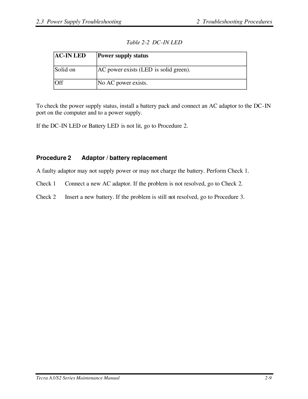
| Table |
|
|
|
|
|
|
|
|
| Power supply status |
|
|
|
|
|
|
|
| Solid on | AC power exists (LED is solid green). |
|
|
|
|
|
|
|
| Off | No AC power exists. |
|
|
|
|
|
|
|
To check the power supply status, install a battery pack and connect an AC adaptor to the
If the
Procedure 2 Adaptor / battery replacement
A faulty adaptor may not supply power or may not charge the battery. Perform Check 1. Check 1 Connect a new AC adaptor. If the problem is not resolved, go to Check 2. Check 2 Insert a new battery. If the problem is still not resolved, go to Procedure 3.
Tecra A3/S2 Series Maintenance Manual |