Toshiba Personal Computer
TOSHIBA CORPORATION
TECRA A3/S2 Maintenance Manual
Copyright
injury if the safety instruction is not observed
The manual is divided into the following parts Chapter
DISKCOPY A B
Chapter 1 Hardware Overview
Table of Contents
Chapter 2 Troubleshooting Procedures
Chapter 3 Tests and Diagnostics
Chapter 4 Replacement Procedures
General
Key Layout
Appendices
Board Layout
Chapter Hardware Overview
1-ii
1 Hardware Overview
Tecra A3/S2 Series Maintenance Manual
Chapter
Contents
Error! Bookmark not defined
1 Hardware Overview
1-iv
Tecra A3/S2 Series Maintenance Manual
1 Hardware Overview
1 Hardware Overview
1.1 Features
1.2 System Unit
1.2 System Unit
? BIOS ? 1MB Flash ROM for system BIOS a Suspend to RAM/Disk
1 Hardware Overview
? Keyboard
1.2 System Unit
1 Hardware Overview
? PCMCIA Card Organization
1 Hardware Overview
1.2 System Unit
? TV-out port
1.2 System Unit
1 Hardware Overview
1.2 System Unit
1.2 System Unit
1 Hardware Overview
1 Hardware Overview
Realtek ALC250VD for AC97 codec
1.2 System Unit
1.2 System Unit
TI PCI7411 Card Bus Host Adapter
1 Hardware Overview
Marvell 88SA8040 for Serial ATA Bridge
Marvell 88E8053 for Giga LAN
Marvell 88E8036 for 10/100M LAN
1.2 System Unit
Tecra A3/S2 Series Maintenance Manual
1.3 2.5-inch Hard Disk Drive
1 Hardware Overview
1.4.1 DVD-ROM Drive
1.4 Optical Devices module
1.4 Removable Drives
1.4.2 CD-ROM Drive
1.4 Removable Drives
1.4.3 CD-RW/DVD-ROM Drive
1 Hardware Overview
1.4.5 DVD Super Multi Drive
1.5 Power Supply
1.4.4 DVD±R/±RW Drive
1 Hardware Overview
1.5 Power Supply
DVD-RAM
Standard rotational speed
1 Hardware Overview
1 Hardware Overview
1.5 Power Supply
1.5 Power Supply
1 Hardware Overview
1.5 Power Supply
6. Power ON/OFF sequence
1.6 Batteries
1.6.1 Main Battery
1.6 Batteries
1 Hardware Overview
1.6 Batteries
1.6.2 RTC battery
1 Hardware Overview
Chapter Troubleshooting Procedures
2-ii
2 Troubleshooting Procedures
Tecra A3/S2 Series Maintenance Manual
Troubleshooting Introduction
Contents
2 Troubleshooting Procedures
Chapter
2 Troubleshooting Procedures
Figures
Tables
2 Troubleshooting Procedures
2.1 Troubleshooting Introduction
2 Troubleshooting Procedures
2.2 Troubleshooting Flowchart
2.3 Power Supply Troubleshooting
2 Troubleshooting Procedures
Figure 2-1 Troubleshooting flowchart 1/2
2.3 Power Supply Troubleshooting
Tecra A3/S2 Series Maintenance Manual
2.3 Power Supply Troubleshooting
Figure 2-1 Troubleshooting flowchart 2/2
2 Troubleshooting Procedures
If the diagnostics program cannot detect an error, the problem may be intermittent. The test program should be executed several times to isolate the problem. When a problem has been located, perform the appropriate troubleshooting procedures as follows
2.3 Power Supply Troubleshooting
2 Troubleshooting Procedures
Other problems that are not covered by the diagnostics program may be discovered by a user
2 Troubleshooting Procedures
2.3 Power Supply Troubleshooting
Figure 2-2 Power Supply Troubleshooting Process
2 Troubleshooting Procedures
Battery State
Procedure 1 Power Status Check
Table 2-1 Battery LED
LED colors
No AC power exists
Power supply status
AC power exists LED is solid green
Procedure 2 Adaptor / battery replacement
Battery
Procedure 3 Power supply connection check
AC power cord
2 Troubleshooting Procedures
2.3 Power Supply Troubleshooting
Procedure 4 Diagnostic check
Procedure 5 Replacement check
2 Troubleshooting Procedures
Figure 2-3 Display troubleshooting process
2.4 Display Troubleshooting
2 Troubleshooting Procedures
2.4 Display Troubleshooting
Procedure 1 External display check
Procedure 2 Diagnostic check
2 Troubleshooting Procedures
2.4 Display Troubleshooting
Procedure 3 Connector and replacement check
2 Troubleshooting Procedures
Figure 2-4 Keyboard troubleshooting process
2.5 Keyboard Troubleshooting
2 Troubleshooting Procedures
2.5 Keyboard Troubleshooting
Procedure 1 External keyboard check
2 Troubleshooting Procedures
Procedure 2 Diagnostic check
Figure 2-5 External USB device troubleshooting process
2.6 External USB Devices Troubleshooting
2 Troubleshooting Procedures
Procedure 1 External device and connection check
Procedure 2 Replace system board
2.6 External USB Devices Troubleshooting
Figure 2-6 TV-out troubleshooting process
2.7 TV-Out Failure Troubleshooting
2 Troubleshooting Procedures
Procedure 1 TV connection check
Procedure 2 TV set check
2.7 TV-Out Failure Troubleshooting
Figure 2-7 Printer port troubleshooting process
2.8 Printer Port Troubleshooting
2 Troubleshooting Procedures
Procedure 3 Replace system board
Procedure 1 Diagnostic check
Procedure 2 Printer port loopback check
2 Troubleshooting Procedures
Figure 2-8 TouchPad troubleshooting process
2.9 TouchPad Troubleshooting
2.9 Touch Pad Troubleshooting
2 Troubleshooting Procedures
Procedure 2 TouchPad replacement check
2.9 TouchPad Troubleshooting
Procedure 1 TouchPad connection check
2 Troubleshooting Procedures
2.9 Touch Pad Troubleshooting
2.10 Speaker Troubleshooting
Figure 2-9 Speaker troubleshooting process
2 Troubleshooting Procedures
Procedure 3 Connection check
Procedure 1 Audio source test
Procedure 2 Earphone test
Procedure 4 Replacement check
2.9 Touch Pad Troubleshooting
2.11 Modem Troubleshooting
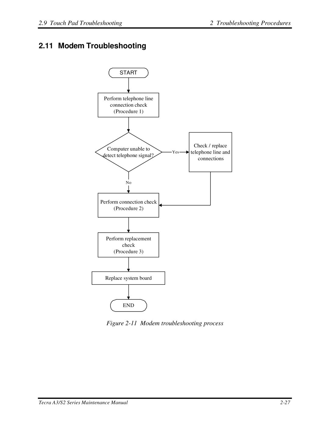
Figure 2-11 Modem troubleshooting process
2 Troubleshooting Procedures
Procedure 3 Modem replacement check
Procedure 1 Telephone line connection check
Procedure 2 Modem card connection check
2 Troubleshooting Procedures
2.9 Touch Pad Troubleshooting
2.12 PCMCIA Troubleshooting
Figure 2-12 PCMCIA troubleshooting process
2 Troubleshooting Procedures
Procedure 1 SYCARD test
Procedure 2 PCMCIA socket replacement check
2.9 TouchPad Troubleshooting
2.9 Touch Pad Troubleshooting
2.13 IEEE 1394 Troubleshooting
Figure 2-13 IEEE 1394 troubleshooting process
2 Troubleshooting Procedures
Procedure 1 IEEE 1394 device check
Procedure 3 Connection and replacement check
2.9 TouchPad Troubleshooting
Tecra A3/S2 Series Maintenance Manual
2.9 Touch Pad Troubleshooting
2 Troubleshooting Procedures
2-33
Figure 2-14 Wireless LAN troubleshooting process
2.14 Wireless LAN Troubleshooting
2.10 Speaker Troubleshooting
2 Troubleshooting Procedures
Procedure 2 Connector and replacement check
Procedure
Diagnostic test
2.10 Speaker Troubleshooting
Tecra A3/S2 Series Maintenance Manual
2 Troubleshooting Procedures
2.10 Speaker Troubleshooting
2-36
Chapter Tests and Diagnostics
3-ii
3. Tests and Diagnostics
Tecra A3/S2 Series Maintenance Manual
3-12
Test and Diagnostic Operation
3-11
3-13
3-iv
3. Tests and Diagnostics
Tecra A3/S2 Series Maintenance Manual
NOTES To start the diagnostics, follow these steps
3.1 The Diagnostic Test
2. Exit this program when you are at Main Menu
3. Tests and Diagnostics
Tecra A3/S2 Series Maintenance Manual
3. Tests and Diagnostics
3.2 Executing the Diagnostic Test
3. Tests and Diagnostics
Executing the Diagnostic Test
The below display will show up at the beginning of T&D program
Tecra A3/S2 Series Maintenance Manual
If an error is detected and a test fails, the following message displays
3.2 Executing the Diagnostic Test
3. Tests and Diagnostics
3.2 Executing the Diagnostic Test
NOTE Press Pause to pause a test and Enter to resume
3. Tests and Diagnostics
Tecra A3/S2 Series Maintenance Manual
3.3 Parallel Port Test
3.3 Config Check Test
3 Tests and Diagnostics
3. Tests and Diagnostics
3.4 DMI Check Test
3.4 DMI Check Test
3. Tests and Diagnostics
3.5 PIO Loopback Test
Tecra A3/S2 Series Maintenance Manual
3.6 IEEE 1394 Test
3. Tests and Diagnostics
3-10
3. Tests and Diagnostics
3.6 Speaker Audio Test
3.7 Speaker Audio Test
3. Tests and Diagnostics
3.7 Fan ON/OFF Test
3.8 Fan ON/OFF Test
3. Tests and Diagnostics
3.8 Main Battery Charge Test
3.9 Main Battery Change Test
NOTE Press “Esc” key can skip the current subtest
3.9 FDD Test
3.10 FDD Test
3 Tests and Diagnostics
3.10 FDD Test
3. Tests and Diagnostics
Tecra A3/S2 Series Maintenance Manual
3-15
3. Tests and Diagnostics
3.10 CD-ROM Test
3.11 CD-ROM Test
NOTE Press “Esc” key can skip the current subtest
3. Tests and Diagnostics
3.11 Keyboard Test
3.12 Keyboard Test
3.12 Keyboard Test
3. Tests and Diagnostics
Tecra A3/S2 Series Maintenance Manual
3-18
3.12 Keyboard Test
3. Tests and Diagnostics
Tecra A3/S2 Series Maintenance Manual
3-19
NOTE The Touch Pad test cannot be used to test an external USB mouse
3.12 Mouse Pad Test
3.13 Mouse Pad Test
3. Tests and Diagnostics
After checking T/Pad buttons and cursor’s function, use “Tab” key or use T/Pad cursor to click the “OK” column will end this test
3. Tests and Diagnostics
3.13 Mouse Pad Test
3. Tests and Diagnostics
3.13 LCD Pixels Mode Test
3.14 LCD Pixels Mode Test
3. Tests and Diagnostics
3.14 Lid Switch Test
3.15 Lid Switch Test
3. Tests and Diagnostics
3.15 HDD R/W Test
3.16 HDD R/W Test
3. Tests and Diagnostics
NOTE Press “Ctrl + Break” keys can terminate the current subtest
NOTE The AC adaptor should be connected to successfully run this test
Tecra A3/S2 Series Maintenance Manual
NOTE LAN loopback needs to plug in before test begins
3.16 LAN Test
3.17 LAN Test
3. Tests and Diagnostics
The screen should display as below, indicating
pass will go on to next test
Tecra A3/S2 Series Maintenance Manual
3.17 LAN Test
3. Tests and Diagnostics
Tecra A3/S2 Series Maintenance Manual
3-28
3.17 LAN Test
3. Tests and Diagnostics
Tecra A3/S2 Series Maintenance Manual
3-29
3. Tests and Diagnostics
3.17 RTC Test
3.19 CD Control Button Test
Chapter Replacement Procedures
4-ii
4 Replacement Procedures
Tecra A3/S2 Series Maintenance Manual
Battery
Contents
4 Replacement Procedures
Chapter
Removing the HDD Module
4 Replacement Procedures
Figures
4 Replacement Procedures
Removing the FL inverter board
Display Assembly
4.1 General
4 Replacement Procedures
Expansion Memory
4 Replacement Procedures
The example below shows FRUs to be removed before the Direct Play button board can be removed and repaired or replaced. The Direct Play button board is overlapped by the top cover which must be removed before the Direct Play button board can be reached. The removable HDD, keyboard, wireless LAN, ODD, modem, and display assembly in turn overlap the top cover. Always starts the disassembly process by removing the battery pack
WARNING To avoid the risk of electric shock or other injury
Safety Precautions
DANGER
3. Never work with wet or damp hands
Before You Begin
4 Replacement Procedures
Disassembly Procedures
Assembly Procedures
Tools and Equipment
4 Replacement Procedures
Figure 4-1 Removing the battery pack
4.2 Battery
Removing the Battery Pack
4 Replacement Procedures
Removing a PC Card
Installing the Battery Pack
4.3 PC Card
4 Replacement Procedures
4 Replacement Procedures Figure 4-2 Removing a PC Card
Tecra A3/S2 Series Maintenance Manual
4.4 HDD
Installing a PC Card
Figure 4-3 Installing a PC Card
4 Replacement Procedures
Removing the HDD Module
Figure 4-5 Removing the HDD door
Tecra A3/S2 Series Maintenance Manual
Disassembling the HDD Module
Installing the HDD Module
Figure 4-6 Removing the HDD module
4 Replacement Procedures
Removing the Optical Drive Module
4 Replacement Procedures Figure 4-7 Removing the HDD bracket
4.5 Optical Drive Module
4 Replacement Procedures
Installing the Optical Drive Module
Figure 4-8 Removing the optical drive module
Figure 4-9 Removing the optical drive bracket
4.6 Optical Drive
Disassembling the Optical Drive
4 Replacement Procedures
4.6 Optical Drive
Reassembling the Optical Drive
Figure 4-10 Removing the wireless LAN cover
4.7 Wireless LAN
Removing the Wireless LAN
4 Replacement Procedures
Figure 4-11 Removing the wireless LAN unit
Installing the Wireless LAN
Figure 4-12 Removing the memory module cover
4.8 Expansion Memory Module
Removing an Expansion Memory
4 Replacement Procedures
7. Replace the battery pack
Figure 4-13 Removing a memory module
4 Replacement Procedures
Tecra A3/S2 Series Maintenance Manual
4 Replacement Procedures
Installing an Expansion Memory Module
Figure 4-14 Removing an expansion memory cover
Tecra A3/S2 Series Maintenance Manual
Figure 4-15 Installing an expansion memory
4 Replacement Procedures
4-22
Figure 4-16 Removing the strip cover
4.9 Keyboard
Removing the Keyboard
4 Replacement Procedures
5. Lift the keyboard out of its bay, revealing the keyboard cable
Figure 4-17 Removing the keyboard
4 Replacement Procedures
4 Replacement Procedures Figure 4-18 Disconnecting the keyboard cable
Installing the Keyboard
Figure 4-19 Removing the Bluetooth
4.10 Bluetooth
Removing the Bluetooth
Installing the Bluetooth
Figure 4-20 Removing the modem module
4.11 Modem
Removing the Modem
4 Replacement Procedures
Removing the Display Assembly
4.12 Display Assembly
Installing the Modem
Figure 4-21 Removing the display assembly screws
4 Replacement Procedures
Figure 4-22 Removing the wireless and LCD cables
Installing the Display Assembly
Removing screws of the bottom
4.13 Top Cover
Removing the Top Cover
4 Replacement Procedures
Figure 4-24 Removing the top cover
Figure 4-25 Removing FFC cables
Tecra A3/S2 Series Maintenance Manual
4 Replacement Procedures
Installing the Top Cover
Figure 4-26 Removing Speaker cables
Removing the Touch Pad
Installing the Touch Pad
4.14 Touch Pad
Figure 4-27 Removing the Touch Pad board
Removing the Speakers
Installing the Speakers
4.15 Speakers
Figure 4-28 Removing the speakers
Figure 4-29 Removing LAN board
4.16 System Board
Removing the LAN Board
4 Replacement Procedures
Figure 4-30 Removing USB board
Installing the LAN Board
Removing the USB Board
4 Replacement Procedures
Figure 4-31 Removing the system board
Installing the USB Board
Removing the System Board
4 Replacement Procedures
Removing the Direct Play Button Board
Installing the System Board
4.17 Direct Play Button Board
Figure 4-32 Removing the Direct Play Button board
Removing the Fan, Heat Sink & CPU
Installing the Direct Play Button Board
4.18 Fan, Heat Sink, & CPU
4 Replacement Procedures
Figure 4-35 Removing the CPU
Figure 4-33 Removing the fan module
Figure 4-34 Removing the heat sink
4 Replacement Procedures
Installing the CPU
4 Replacement Procedures
Figure 4-36 Removing the display mask
4.19 Display Mask
Removing the Display Mask
4 Replacement Procedures
Tecra A3/S2 Series Maintenance Manual
Installing the Display Mask
4 Replacement Procedures
1. Seat the display mask and secure the snaps on each side
Figure 4-37 Removing the LCD module-1
4.20 LCD Module
Removing the LCD Module
4 Replacement Procedures
Installing the LCD Module
Figure 4-38 Removing the LCD module-2
Removing the FL Inverter Board
Installing the FL Inverter Board
4.21 FL Inverter Board
Figure 4-39 Removing the FL inverter board
Precautions for handling the LCD module
Appendix A Handling the LCD Module
3. If the panel’s surface gets dirty, wipe it with cotton or a soft cloth. If it is still dirty, try breathing on the surface to create a light condensate and wipe it again
5. Glass is used in the panel, so be careful not to drop it or let it strike a hard object, which could cause breakage or cracks
7. Do not expose the module to direct sunlight or strong ultraviolet rays for long periods
TECRA A3/S2 Series Maintenance Manual
Figure B-1 System board FRDSY* layout Top
Appendix B Board Layout
B.1 System Board FRDSY* Top View
TECRA A3/S2 Series Maintenance Manual
B.2 System Board FRDSY* Button View
Figure B-2 System board FRDSY* layout Button
Mark
Table B-1 System board ICs top and bottom
TECRA A3/S2 Series Maintenance Manual
Number
Number
Table B-2 System board connectors top and bottom
TECRA A3/S2 Series Maintenance Manual
Name
Table C-1 SODIMM I/F pin assignments 200-PIN 1/4
Appendix C Pin Assignments
System Board C.1 JP24,JP25
Signal name
Signal Name
Table C-1 SODIMM I/F pin assignments 200-PIN 2/4
Signal name
TECRA A3/S2 Series Maintenance Manual
Signal Name
Table C-1 SODIMM I/F pin assignments 200-PIN 3/4
Signal name
TECRA A3/S2 Series Maintenance Manual
Signal Name
Table C-1 SODIMM I/F pin assignments 200-PIN 4/4
Signal name
TECRA A3/S2 Series Maintenance Manual
Signal name
C.2 JP1
Table C-2 RGB I/F pin assignments 15-pin
Signal Name
Signal name
C.3 JP18
Table C-3 HDD I/F pin assignments 44-pin
Signal Name
Signal name
C.4 JP31
Table C-4 ODD I/F pin assignments 50-pin
Signal Name
Signal name
C.5 JP19
Table C-5 PC Card I/F pin assignments 84-pin 1/2
Signal Name
S1D8
TECRA A3/S2 Series Maintenance Manual
S1D0
Signal Name
Table C-5 PC Card I/F pin assignments 84-pin 2/2
Signal name
TECRA A3/S2 Series Maintenance Manual
Signal name
C.6 JP28
Table C-6 Mini PCI I/F pin assignments 124-pin 1/2
Signal Name
TECRA A3/S2 Series Maintenance Manual
C-12
Signal Name
Table C-6 Mini PCI I/F pin assignments 124-pin2/2
Signal name
TECRA A3/S2 Series Maintenance Manual
C-14
TECRA A3/S2 Series Maintenance Manual
C.7 JP6
Signal name
Pin No
Signal Name
C.8 JP29
Signal name
TECRA A3/S2 Series Maintenance Manual
C.10 PJP1
Table C-10 AC Adaptor Connector pin assignments 3-pin
C.9 JP12
Table C-9-1 JP12 Fan I/F pin assignments 3-pin
C.12 JP22
Table C-12 Headphone Connector pin assignments 6-pin
C.11 JP21
Table C-11 Microphone I/F pin assignments 6-pin
TECRA A3/S2 Series Maintenance Manual
Appendix D Keyboard Scan/Character Codes
Table D-1 Scan codes set 1 and set 2 1/4
Keytop
Keytop
Table D-1 Scan codes set 1 and set 2 2/4
TECRA A3/S2 Series Maintenance Manual
Code set
Keytop
Table D-1 Scan codes set 1 and set 2 3/4
TECRA A3/S2 Series Maintenance Manual
Code set
Table D-1 Scan codes set 1 and set 2 4/4
1. * Scan codes differ by mode
Table D-2
Scan codes with left Shift key
TECRA A3/S2 Series Maintenance Manual
Table D-3 Scan codes in Numlock mode
Table D-4 Scan codes with Fn key
Code set
TECRA A3/S2 Series Maintenance Manual
Table D-5 Scan codes in overlay mode
Table D-6 No.124 key scan code
Keytop
Key top
Table D-7 No.126 key scan code
TECRA A3/S2 Series Maintenance Manual
Shift
Figure E-1 US keyboard
Appendix E Key Layout
E.1 United States US Keyboard
TECRA A3/S2 Series Maintenance Manual
E.2 United Kingdom UK Keyboard
Figure E-2 UK keyboard
Figure E-3 SP keyboard
E.3 Spanish SP Keyboard
E.4 Japanese JA Keyboard
Figure E-4 JA keyboard
TECRA A3/S2 Series Maintenance Manual
E.5 Korean KO Keyboard
Figure E-5 KO keyboard
TECRA A3/S2 Series Maintenance Manual
E.6 French FR Keyboard
Figure E-6 FR keyboard
Figure E-7 FR-C keyboard
E.7 French-Canadian Keyboard
E.8 Portuguese Keyboard
Figure E8 Portuguese keyboard
Figure E-9 US-INTE Keyboard
E.9 US-INTERNATIONAL Keyboard
E.10 GreeceGR Keyboard
Figure E-10 GR keyboard
Figure E-11 CH-T keyboard
E.11 Chinese-T Keyboard
E.12 Swedish Keyboard
Figure E-12 Swedish keyboard
Figure E-13 IT keyboard
E.13 ITALIAN Keyboard
E.14 CZECH Keyboard
Figure E-14 Czech keyboard
TECRA A3/S2 Series Maintenance Manual
E-10
Series Screw Torque List
Appendix F Series Screw Torque List
Table F-1
TECRA A3/S2 Series Maintenance Manual
Page
SCREW SPEC
TECRA A3/S2 Series Maintenance Manual
SCREW P/N
LOCATION
TECRA A3/S2 Series Maintenance Manual
Appendix G Reliability
Table G-1 MTBF
Component
TECRA A3/S2 Series Maintenance Manual