Manuals
/
Brands
/
Computer Equipment
/
Webcam
/
Toshiba
/
Computer Equipment
/
Webcam
Toshiba
TOSHIBA NB100
Appendix E Key Layout
1
206
211
211
Download
211 pages, 3.67 Mb
Apx. E Key Layout
Appendices
TOSHIBA NB
100 Mainte
nance Manu
al
E-1
Apx. E
Key Layout
Appendix E
Key Layout
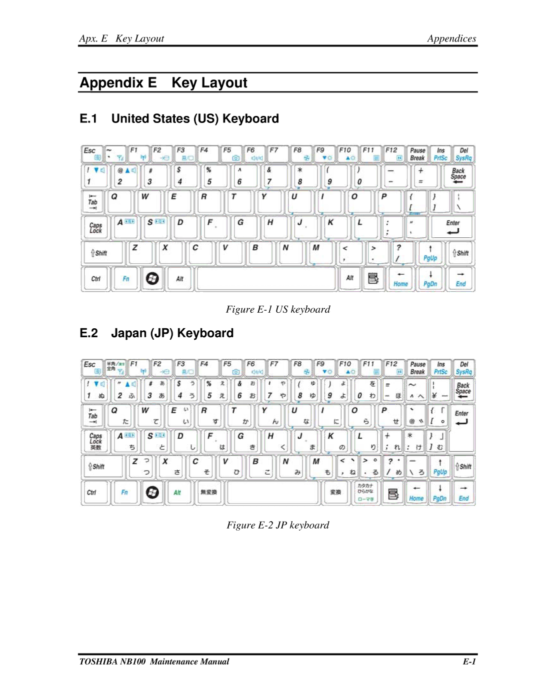
E.1
United States (US) Keyboard
Figure E-1 US keyboard
E.2
Japan (JP) Keyboard
Figure E-2 JP keyboard
Contents
Main
Page
Preface
Page
Page
Table of Contents
Page
Page
Page
Page
Page
Page
Page
Chapter 1 Contents
Page
1.1 Features
Page
Page
Page
Page
Page
Page
Page
Page
Page
Page
1.3 2.5-inch HDD
1.4 Solid State Drive (SSD)
1.5 Power Supply
1.6 Batteries
Page
Page
Chapter 2 Contents
Page
Page
2.1 Outline
2.2 Basic Flowchart
Page
Page
Page
2.3 Power Supply
Page
Page
2.4 System Board
Page
2.5 HDD
Page
Page
Page
2.6 Keyboard
2.7 Display
Page
2.8 LAN
2.9 Audio Test
2.10 Cooling Module
Page
Page
Chapter 3 Contents
Page
Page
3.1 General
Arizona 10
Page
3.2 Quick Start
Page
Page
Page
Page
Page
Page
Page
Page
Page
Page
Page
3.3 Options
Page
Page
Page
Page
Page
Page
Page
Page
DIAG REPORT
Page
3 Diagnostic Programs 3.4 Subtests
3.4 Subtests
Parity [ Parity
3.4 Subtests 3 Diagnostic Programs
Page
3.5 System Test
Page
Page
Page
Page
3.6 Memory Test
Page
Page
Page
Page
Page
3.7 Storage
Page
Page
Page
3.8 Video
Page
Page
Page
Page
Page
Page
Page
Page
3.9 Communication (COMM)
3.10 Peripheral
Page
Page
3.11Error Codes and Description 3 Diagnostic Programs
3.11 Error Codes and description
Page
Page
Page
Page
Page
3.12 Quick Test Item List 3 Diagnostic Programs
3.12 Quick Test Item List
Chapter 4 Replacement Procedures
Page
Chapter 4 Contents
Page
Page
4.1 General
Page
Page
Page
Page
Page
Page
Page
Page
Page
Page
Page
Page
4.2 Keyboard Cover and Keyboard
Page
Page
4.3 Wireless LAN Card
Page
4.4 Display Assembly
Page
Page
4.5 Top Cover
Page
4.6 SSD/HDD and Fan
Page
Page
4.7 System Board, DC-IN, RJ-45 Cable and Blue-Tooth Card
Page
Page
4.8 Display Mask
Page
Page
Page
Page
Page
4.9 LCD Module
Page
Page
Page
4.10 CCD Board and Speakers
Page
Page
Page
4.11 Touch Pad Board
Page
Page
Page
Page
Page
Appendix A Handling the LCD Module
Precautions for handling the LCD module
Page
Page
Page
Page
Page
Page
Page
Appendix C Pin Assignments
C.1 CN1 CRT Connector (15-Pin)
C.2 CN2 Battery Connector (6-Pin)
C.3 CN3 LCD+ Web CAM Connector (40-Pin)
C.4 CN4 WWAN Connector (52-Pin)
C.5 CN5 DC-IN Connector (4-Pin)
C.6 CN6 Internal Keyboard Connector (24-Pin)
C.7 CN7 Speaker Cable Connector (4-Pin)
C.8 CN8 Touch Pad Connector (12-Pin)
C.9 CN9 Fan Connector (3-Pin)
C.10 CN10 Bluetooth Cable Connector (10-Pin)
C.11 CN500 USB Port#1 Connector (4-Pin)
C.12 CN501 USB Port#2 Connector (4-Pin)
C.13 CN502 RTC Battery Connector 2-Pin)
C.14 CN503 Card Reader Connector (21-Pin)
C.15 CN504 DDR2 DIMM0 Socket (200-Pin)
Page
Page
C.16 CN505 HDD Connector (22-Pin)
C.17 CN507 Touch Pad Connector (12-Pin)
C.18 CN508 Touch Pad Board Connector (14-Pin)
C.19 CN509 Mini Card Connector (52-Pin)
C.20 CN510 USB Port#3 Connector (4-Pin)
C.21 JACK1 External Micro Phone Connector (6-Pin)
C.22 JACK2 Head Phone Connector (6-Pin)
C.23 JACK500 RJ45 Connector (9-Pin)
Keyboard Scan/Character Codes Appendices
Appendix D Keyboard Scan/Character Codes
Table D-1 Scan codes (set 1 and set 2) (1/4)
Appendices Keyboard Scan/Character Codes
Table D-1 Scan codes (set 1 and set 2) (2/4)
Keyboard Scan/Character Codes Appendices
Table D-1 Scan codes (set 1 and set 2) (3/4)
Page
Page
Page
Keyboard Scan/Character Codes Appendices
Table D-5 Scan codes in overlay mode
*: This key is for UK keyboard only. Table D-6 No.124 key scan code
Page
Appendix E Key Layout