period four
Chiller-Plant Control
notes
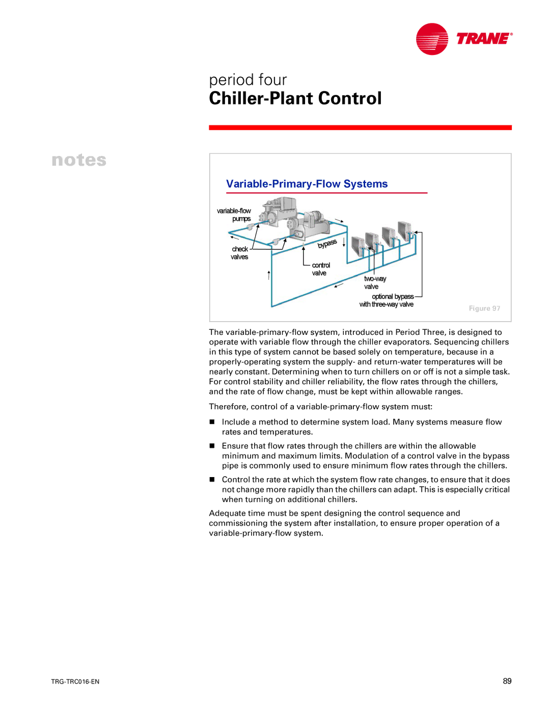
Variable-Primary-Flow Systems
|
| |
pumps |
|
|
check |
|
|
|
| |
|
| |
valves |
|
|
control |
|
|
valve |
| |
|
| |
| valve |
|
| optional bypass |
|
| Figure 97 | |
|
|
The
Therefore, control of a
nInclude a method to determine system load. Many systems measure flow rates and temperatures.
nEnsure that flow rates through the chillers are within the allowable minimum and maximum limits. Modulation of a control valve in the bypass pipe is commonly used to ensure minimum flow rates through the chillers.
nControl the rate at which the system flow rate changes, to ensure that it does not change more rapidly than the chillers can adapt. This is especially critical when turning on additional chillers.
Adequate time must be spent designing the control sequence and commissioning the system after installation, to ensure proper operation of a
89 |