period four
Chiller-Plant Control
notes
chiller safeties must be capable of shutting the chiller down to avoid equipment damage.
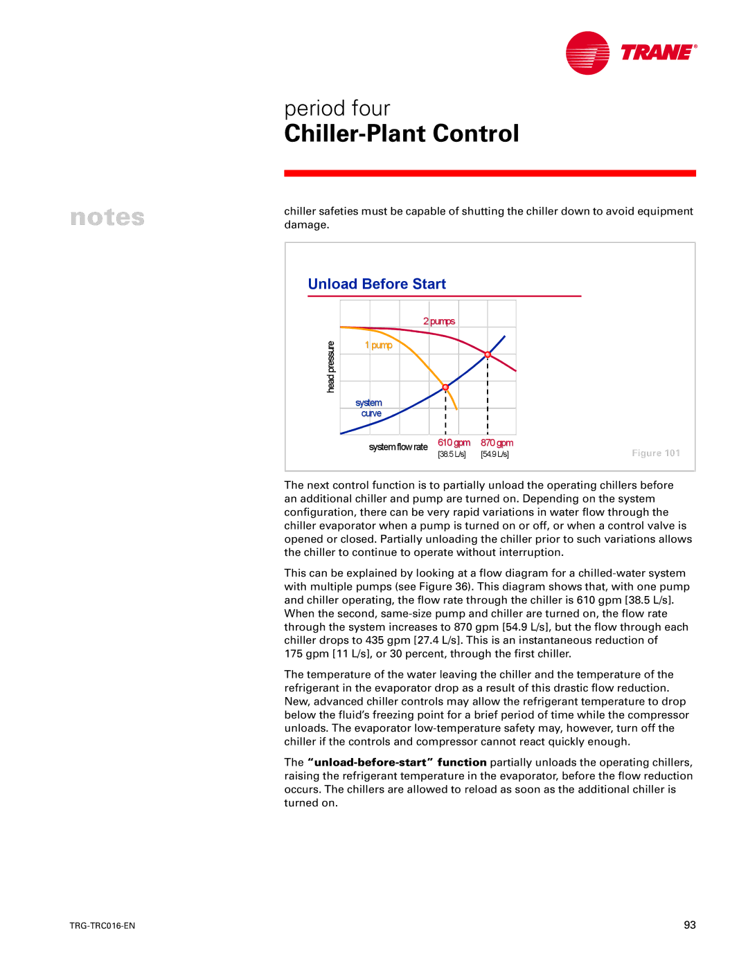
Unload Before Start |
|
| ||
| 2pumps |
|
| |
headpressure | 1pump |
|
|
|
|
|
|
| |
| system |
|
|
|
| curve |
|
|
|
| system flowrate | 610gpm | 870gpm | Figure 101 |
|
| [38.5L/s] | [54.9L/s] | |
The next control function is to partially unload the operating chillers before an additional chiller and pump are turned on. Depending on the system configuration, there can be very rapid variations in water flow through the chiller evaporator when a pump is turned on or off, or when a control valve is opened or closed. Partially unloading the chiller prior to such variations allows the chiller to continue to operate without interruption.
This can be explained by looking at a flow diagram for a
When the second,
175 gpm [11 L/s], or 30 percent, through the first chiller.
The temperature of the water leaving the chiller and the temperature of the refrigerant in the evaporator drop as a result of this drastic flow reduction. New, advanced chiller controls may allow the refrigerant temperature to drop below the fluid’s freezing point for a brief period of time while the compressor unloads. The evaporator
The
93 |