period two
Chilled-Water System Design
notes
Primary-Secondary Configuration
production |
|
|
|
|
|
pumps |
|
|
|
|
|
|
|
|
|
| e |
|
|
|
| ip | |
|
|
| p |
| |
|
| ss |
|
| |
| a |
|
|
| |
yp |
|
|
|
| |
b |
|
|
|
|
|
production loop ![]()
distribution loop
distribution pump
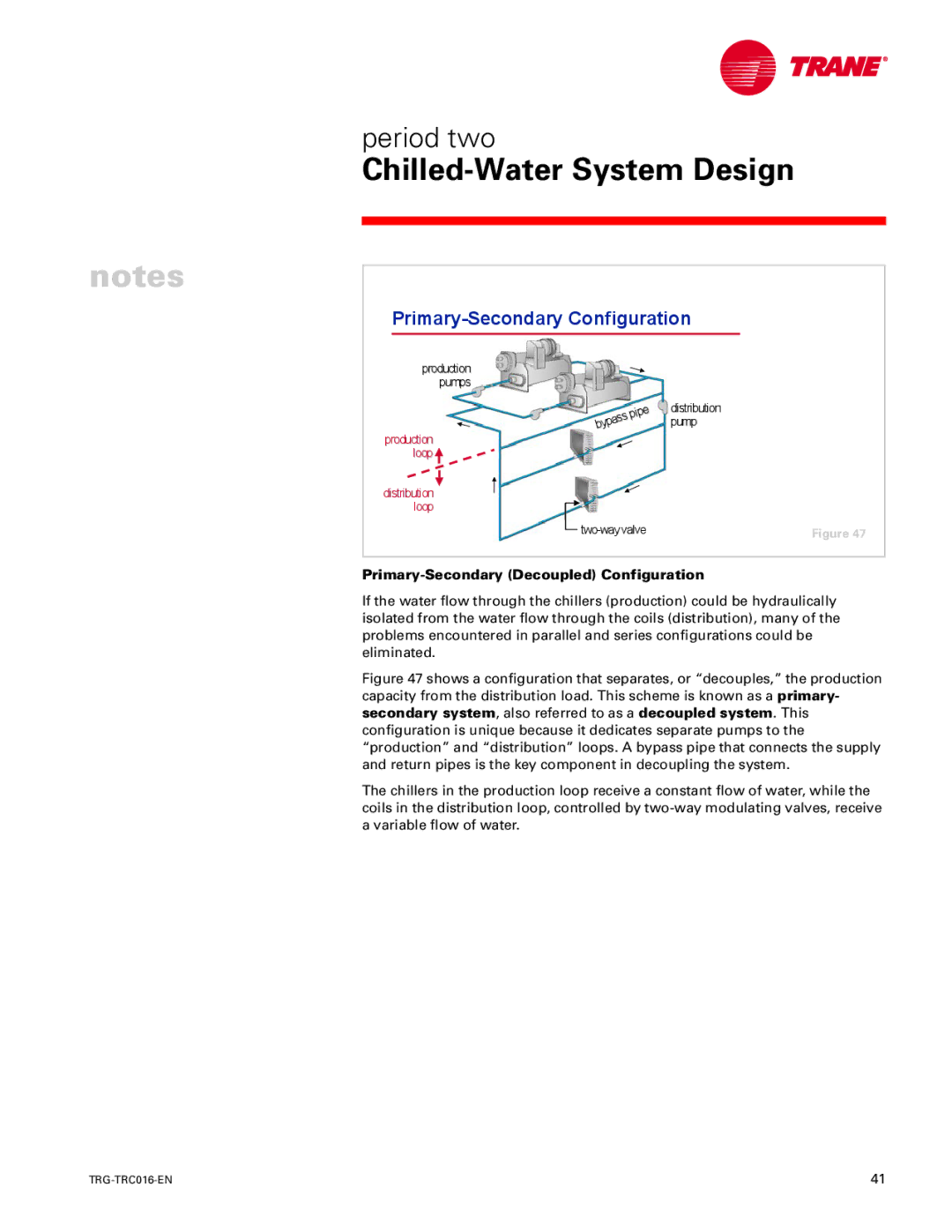
Figure 47
Primary-Secondary (Decoupled) Configuration
If the water flow through the chillers (production) could be hydraulically isolated from the water flow through the coils (distribution), many of the problems encountered in parallel and series configurations could be eliminated.
Figure 47 shows a configuration that separates, or “decouples,” the production capacity from the distribution load. This scheme is known as a primary- secondary system, also referred to as a decoupled system. This configuration is unique because it dedicates separate pumps to the “production” and “distribution” loops. A bypass pipe that connects the supply and return pipes is the key component in decoupling the system.
The chillers in the production loop receive a constant flow of water, while the coils in the distribution loop, controlled by two-way modulating valves, receive a variable flow of water.
41 |
