RJ-45 Connector Pin Assignments
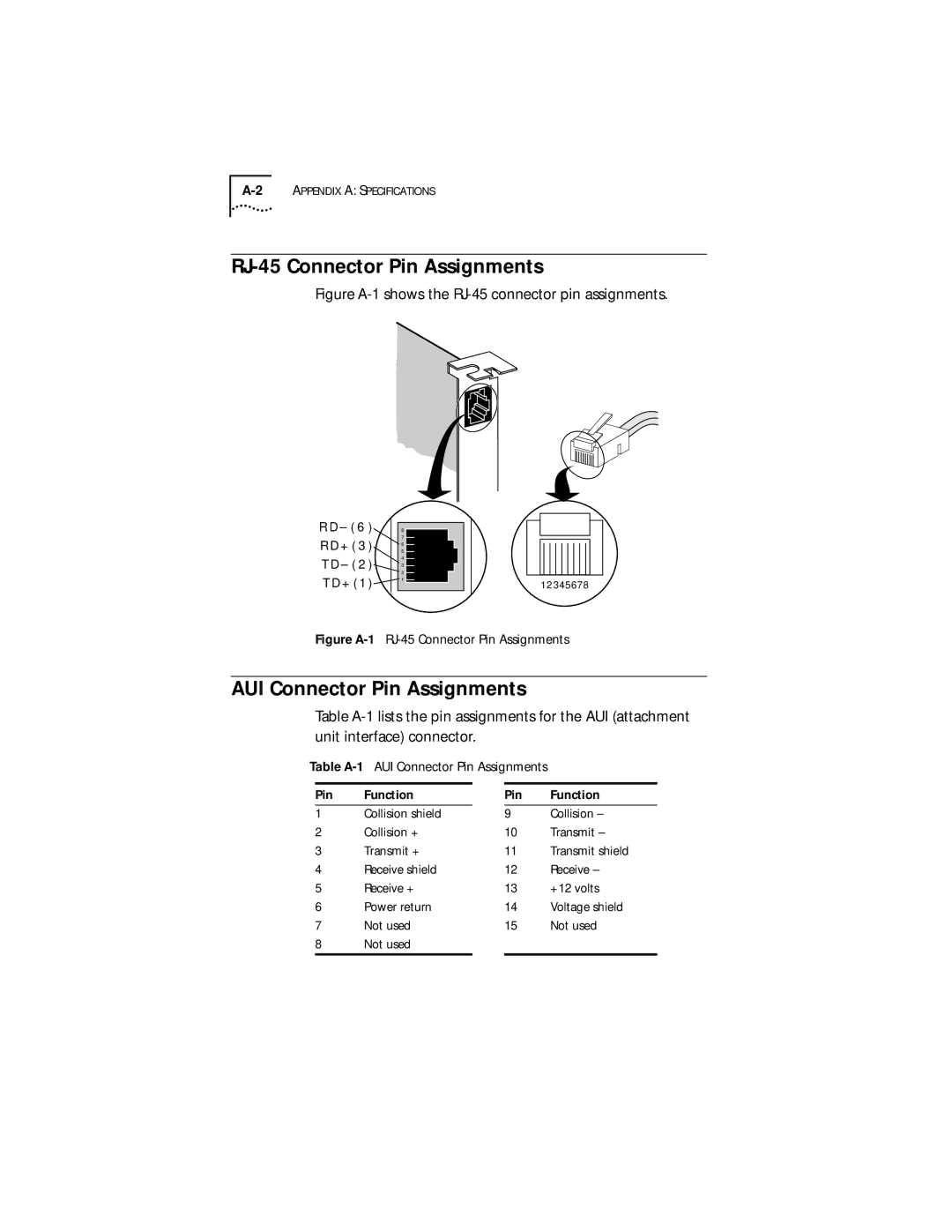
Figure A-1 shows the RJ-45 connector pin assignments.
R D – ( 6 ) R D + ( 3 ) T D – ( 2 ) T D + ( 1 )
8
7
6
5
4
3
2
1
12 345678
Figure A-1 RJ-45 Connector Pin Assignments
AUI Connector Pin Assignments
Table
Table
Pin Function
1Collision shield
2Collision +
3Transmit +
4Receive shield
5Receive +
6Power return
7Not used
8Not used
Pin Function
9Collision –
10Transmit –
11Transmit shield
12Receive –
13+12 volts
14Voltage shield
15Not used