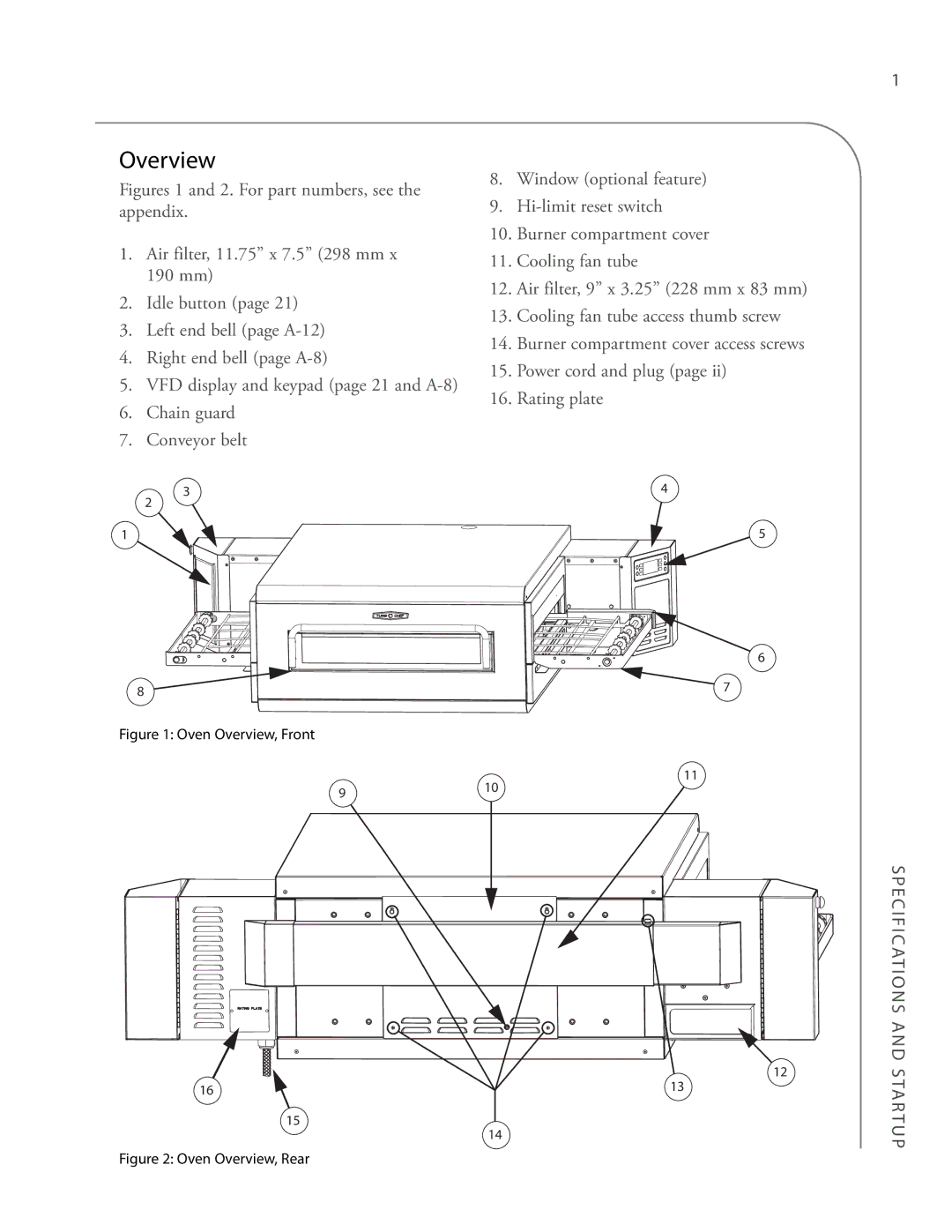
3240 specifications
Turbo Chef Technologies 3240 is a cutting-edge cooking appliance that embodies innovation and efficiency for commercial kitchens. Designed to meet the demands of the modern food service industry, this versatile solution combines advanced cooking technologies to deliver outstanding performance while ensuring culinary excellence.At the heart of the Turbo Chef 3240 is the patented High Speed Hybrid Technology. This system integrates rapid cook air impingement with microwave cooking, allowing for faster cooking times without compromising quality. The result is perfectly cooked food that retains its moisture and flavor, making it an ideal choice for restaurants, cafes, and other food service establishments that require quick turnaround without sacrificing taste.
One of the standout features of the Turbo Chef 3240 is its sleek, compact design. The unit is built to maximize kitchen space while providing a generous cooking capacity. With a user-friendly interface and touchscreen controls, operators can effortlessly navigate through various cooking modes, adjust settings, and monitor cooking progress. This ease of use is particularly beneficial in high-pressure environments where efficiency is paramount.
Another key characteristic of the Turbo Chef 3240 is its exceptional versatility. It can handle a wide range of menu items, from pizzas and baked goods to proteins and vegetables. With multiple cooking modes, including rethermalization, toasting, and baking, the Turbo Chef 3240 is equipped to handle any culinary challenge. Additionally, the ability to program custom recipes allows chefs to maintain consistency and quality across their offerings.
Energy efficiency is also a significant consideration in the design of the Turbo Chef 3240. The appliance is engineered to use less energy than traditional cooking methods, making it a responsible choice for businesses looking to reduce their environmental footprint. This commitment to sustainability does not come at the expense of performance; instead, it enhances the overall efficiency of the kitchen.
Durability is another hallmark of the Turbo Chef 3240. Constructed with high-grade materials, this unit is designed to withstand the rigors of daily use in a commercial environment. Maintenance is simplified, with accessible components that facilitate cleaning and upkeep, ensuring that the unit remains in optimal condition.
In conclusion, the Turbo Chef Technologies 3240 stands out as an innovative solution for commercial kitchens, combining speed, versatility, and energy efficiency in one powerful appliance. Whether for small cafes or large restaurants, the Turbo Chef 3240 provides a reliable way to enhance culinary offerings while streamlining kitchen operations.

