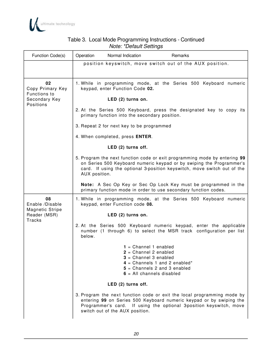
Table 3. Local Mode Programming Instructions - Continued
Note: *Default Settings
Function Code(s) | Operation | Normal Indication | Remarks | |
|
|
| ||
|
| p o s i t i o n k e y s w i t c h , m o v e s w i t c h o u t o f t h e A U X p o s i t i o n . | ||
|
|
| ||
02 | 1. | While in programming mode, at the Series 500 Keyboard numeric | ||
Copy Primary Key |
| keypad, enter Function Code 02. |
| |
Functions to |
|
|
|
|
Secondary Key |
|
| LED (2) turns on. |
|
Positions |
|
|
|
|
| 2. | At the Series 500 Keyboard, press the designated key to copy its | ||
|
| primary function into the secondary position. | ||
| 3. | Repeat 2 for next key to be programmed |
| |
| 4. | When completed, press ENTER. |
| |
|
|
| LED (2) turns off. |
|
| 5. | Program the next function code or exit programming mode by entering 99 | ||
|
| on Series 500 Keyboard numeric keypad or by swiping the Programmer's | ||
|
| card. If using the optional | ||
|
| AUX position. |
| |
|
| Note: A Sec Op Key or Sec Op Lock Key must be programmed in the | ||
|
| primary function mode in order to use secondary function codes. | ||
|
|
| ||
08 | 1. | While in programming mode, at the Series 500 Keyboard numeric | ||
Enable /Disable |
| keypad, enter Function code 08. |
| |
Magnetic Stripe |
|
|
|
|
Reader (MSR) |
|
| LED (2) turns on. |
|
Tracks |
|
|
|
|
2.At the Series 500 Keyboard numeric keypad, enter the applicable number (1 through 6) to select the MSR track configuration per list below.
1 = Channel 1 enabled
2 = Channel 2 enabled
3 = Channel 3 enabled
4 = Channels 1 and 2 enabled*
5 = Channels 2 and 3 enabled
6 = All channels disabled
LED (2) turns off.
3.Program the nex t function code or exit the local programming mode by entering 99 on Series 500 Keyboard numeric keypad or by swiping the Programmer's card. If using the optional
20
