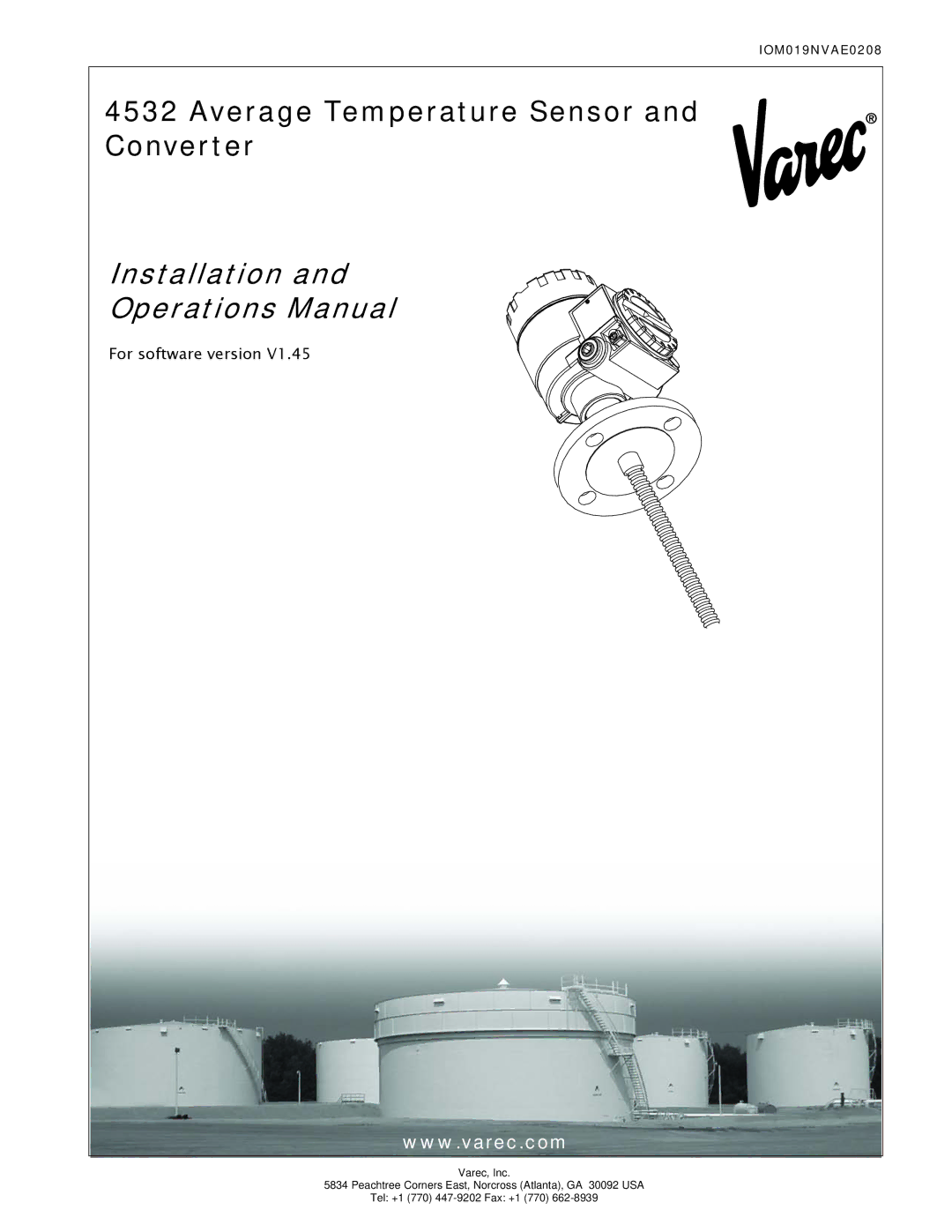
Main
Page
Copyright
Trademarks acknowledged
Disclaimer of Warranties
Limitations of Seller's Liability
Terms of Use
Page
Page
Contents
1 Introduction
2 Safety instructions
3 Identification
4 Installation
6 W i r i n g
7 Operating
8 Operation and Description of Instrument Function . . . . . . . 31
9 M a i n t e n a n c e
Page
Page
1 Introduction
1.1 Introduction
1.2 Installation and operation overview
1.3 Software history
Introduction Average Temperature/Water Bottom Sensor and Converter
1.4 System functional diagram
Level Temperature
Pressure
Figure 1-1: Connection with 7500 Series Radar Tank Gauge and 6000 Series Servo Tank Gauge
FuelsManager Software
2 Safety instructions
2.1 Installation, commissioning and operation
integral part
2.2 Product Requirements 2.2.1 Power source
2.2.2 Use in hazardous areas
2.3.2 Power supply
2.3.3 Grounding
2.3.4 Wiring
2.4 Return
2.5 Disposal
2.6 Notes on safety conventions and symbols
Warning!
Caution!
Note!
EX
Page
Varec, Inc. 7
4532 Identification
Order Code
3 Identification
3.1 Device designation 3.1.1 Nameplate
Figure 3-1: 4532 ATC labels
Figure 3-2: Product label for 453x average temperature devices
3.2 Scope of delivery
3.3 CE marks, declaration of conformity
Varec, Inc. 9
4532 Installation
4 Installation
4.1 Design, dimensions
Figure 4-1: 4532 ATC dimensions
4.2 Unpacking
4.4 Installation Instructions
4.5 Special conditions for safe use
Page
5 Mounting
5.1 Mounting instruction
Figure 5-1: The 4532 ATC mounting
5.2 Mounting on a fixed roof tank
5.2.1 Top anchor method
Figure 5-2: Top anchor application
Figure 5-3: Tensioning wire mounting
Figure 5-4: Top anchor mounting
5.2.2 Thermo well method
Figure 5-5: Thermo well application
5.2.3 Anchor weight method
Figure 5-6: Anchor weight application
Page
5.3 Mounting on a floating roof tank
5.3.1 Top anchor method
Figure 5-8: Top anchor application
Mounting Average Temperature/Water Bottom Sensor and Converter
20 Installation and Operations Manual
5.3.2 Thermo well method
The flexible tube is inserted into a thermo well in the fixed pipe.
Figure 5-9: Thermo well application
The installation procedure is the same as for mounting on a fixed roof tank using the thermo well.
500mm (19.69")
5.3.3 Guide ring and anchor weight method
Figure 5-10:Guide ring and anchor weight application
Page
Varec, Inc. 23
4532 Wiring
6 Wiring
6.1 Terminal Connection 6.1.1 4532 ATC terminal
Figure 6-1: 4532 ATC terminal
Wiring Average Temperature/Water Bottom Sensor and Converter
24 Installation and Operations Manual
6.1.2 6000 Series Servo Tank Gauge terminal
mA
24V
From 4535 ATC
Figure 6-2: 6000 Series Servo Tank Gauge terminal
6.2 Grounding
Figure 6-4: The 4532 ATC Grounding
Page
7 Operating
7.1 Local HART connection 7.1.1 As a Varec tank gauging instrument
7.1.2 As a standalone generic HART instrument
7.2 Device set up: 4590 TSM
7.2.1 HART scanner
7.2.2 The 4532 ATC specific parameter set up on the 4590 TSM
7.3 Device set up: 6000 Series Servo Tank Gauge
7.3.1 Preparation of 6000 Series Servo Tank Gauge
7.3.2 4532 ATC configuration on 6000 Series Servo Tank Gauge
Page
Page
8 Operation and Description of Instrument Function
8.0.1 HART Device designation
8.0.2 Device Data
8.1 Temperature measurement 8.1.1 Primary values: VH00 ~ VH09
8.1.2 Element Temperature 1: VH10 ~ VH15
8.1.3 Element Temperature 2: VH20 ~ VH29
Page
Page
8.1.4 Element Position 1: VH30 ~ VH35 (VH36~VH39 is used only in 4539 ATC)
8.1.5 Element Position 2: VH40 ~ VH45 are not available in 4532 ATC
Page
8.1.6 WB primary and Advanced temp: VH50 ~ VH59
8.1.7 WB Adjustment and Operation Power: VH60 ~ VH69
8.1.8 Temperature Adjustment: VH70 ~ VH79
Page
Page
Page
Page
8.1.9 Device setting 2: VH90~VH99
Page
9 Maintenance
9.1 Exterior cleaning
9.2 Repairs
9.3 Repairs to Ex-approved devices
9.4 Replacement
Varec, Inc. 47
10 Troubleshooting
10.1 System error messages
10.2 Spare parts
Figure 10-1:Spare Parts
11 Accessories
11.1 Anchor weight (Tall profile)
Figure 11-1:Anchor weight dimension
11.2 Anchor weight (Low profile)
Figure 11-2:Low profile anchor weight dimension
11.3 Wire hook, Top anchor
Figure 11-3:Wire hook dimension
Figure 11-4:Top anchor dimension
Varec, Inc. 51
12 Technical data
Technical data at a glance:
Page
Varec, Inc. 53
4532 Order Structure
A Order Structure
Page
Varec, Inc. 55
4532 Declaration of Contamination Form
Declaration of Contamination
B Declaration of Contamination Form
Page
Index