Wiring | Average Temperature/Water Bottom Sensor and Converter |
|
|
6.1.26000 Series Servo Tank Gauge terminal
Since the 4532 ATC is an intrinsically safe instrument, the terminal connection to the Ex i side on HART connection is allowed on the 6000 Series Servo Tank Gauge terminal housing.
L | 1 |
ARS | |
| 2 |
G ARS | |
| 3 |
N ARS | |
L![]()
N
G
Power supply
AC 85 ... 264V 50/60Hz or
DC 20 ... 62V AC20 ... 55V
4 | + Port_B+ | 10 | |
_ | Non IS HART R | ||
5 | to NRF or others | 11 | |
| Port_B- | ||
6 | + | Digital output | 12 |
_ | Rack bus RS485, | ||
7 | orSerial pulse, | 13 | |
+ | HART R | ||
8 |
| 14 | |
| Alarm contact | ||
| _ | 15 | |
9 |
| ||
|
| ||
+
_ ![]() Alarm contact
Alarm contact
+
_ ![]() Alarm contact
Alarm contact
+
_ ![]() Alarm contact
Alarm contact
16 | COM |
|
| 22 | + | 4 ... 20 mA | ||
17 | HOIST | Operation | 23 | _ | Channel 2 | |||
|
| contact |
|
|
|
| ||
18 |
|
| input | 24 + |
|
|
| |
STOP |
| Port_A+ |
|
| ||||
|
|
|
|
| A | IS HART | R | or |
19 |
|
|
| 25 | _ |
| ||
|
|
| Port_A- |
|
| |||
| + |
|
|
| B |
|
|
|
20 | 4 ... 20 mA | 26 | b |
|
|
| ||
| _ |
|
|
|
|
| ||
21 | Channel 1 | From 4535 ATC | ||||||
|
|
|
| |||||
L | ARS | 1 L | |
G | ARS | 2 N | |
N | ARS | 3 GND | |
5 | NRF- | NRF + | |
|
|
| 4 |
RC A/+ RC B/- 7 | |||
|
|
| 6 |
9 | AL1 AL1 | 8 | |
11 | AL2 AL2 | 10 | |
13 | AL3 AL3 | 12 | |
14 16 18 20 22
26 | b |
25PA- B |
24PA+ A |
OT2+ | OT2- | 23 |
OT1+ | OT1- | 21 |
COM CTR2 | CTR1 N.C. | 17 19 |
AL4 | AL4 | 15 |
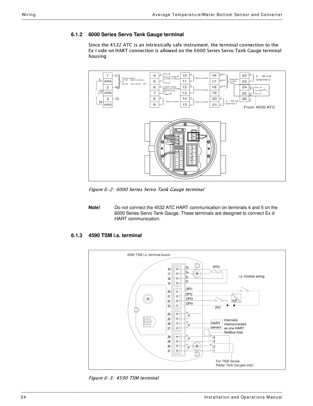
Figure 6-2: 6000 Series Servo Tank Gauge terminal
Note! Do not connect the 4532 ATC HART communication on terminals 4 and 5 on the 6000 Series Servo Tank Gauge. These terminals are designed to connect Ex d HART communication.
6.1.34590 TSM i.s. terminal
4590 TSM i.s. terminal board
mA
24V
For 7500 Series
Radar Tank Gauges only!
Figure 6-3: 4590 TSM terminal
24 | Installation and Operations Manual |