Hardware

TankGate Interface


2.2.3.2COM1 (RS-232/RS-485) (J5)

Note! On some versions of the TankGate, COM1 is not available

RS-232 is one of the two types of high-speed serial communications channels available to interface to Host systems using several different protocols. RS-232 will operate at distances up to 100 feet, while RS-485 allows multidrop communications at distances up to 4000 feet. RS-232 can be used for flexibility in configuring other types of communications links. Other variations of RS-232 communications interfaces include radio, modem and fiber optic interfaces.

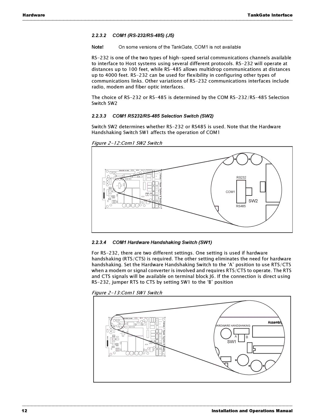
The choice of RS-232 or RS-485 is determined by the COM RS-232/RS-485 Selection

Switch SW2

2.2.3.3COM1 RS232/RS-485 Selection Switch (SW2)

Switch SW2 determines whether RS-232 or RS485 is used. Note that the Hardware

Handshaking Switch SW1 affects the operation of COM1

Figure 2-12:Com1 SW2 Switch


EARTH


A B

NEUTRAL


LINE


RS232


SURGE GND

RS232

+

VFIELD


-


COM1


A/TXD


RS485

B/RXD


GND

COM1

COM1


RTS


CTS


TXD


RXD

COM 0 AUX

SW2


GND


+15V


+5V

POWER

RS485


GND


-15V


2.2.3.4COM1 Hardware Handshaking Switch (SW1)

For RS-232, there are two different settings. One setting is used if hardware handshaking (RTS/CTS) is required. The other setting eliminates the need for hardware handshaking. Set the Hardware Handshaking Switch to the ‘A’ position to use RTS/CTS when a modem or signal converter is involved and requires RTS/CTS to operate. The RTS and CTS signals will be available on terminal block J6. If the connection is direct using RS-232, jumper RTS to CTS by setting SW1 to the ‘B’ position

Figure 2-13:Com1 SW1 Switch


EARTH


A B

NEUTRAL


LINE


HARDWARE HANDSHAKING


SURGE GND

RS232

+

VFIELD


-


COM1


A/TXD


A

B

RS485

B/RXD


GND

COM1


RTS


SW1


CTS


TXD


RXD

COM


0


GND


+15V

AUX


+5V

POWER


GND


-15V


12

Installation and Operations Manual

Page 22
Image 22
Varec 8315 Series manual 3.2 COM1 RS-232/RS-485 J5, 3.3 COM1 RS232/RS-485 Selection Switch SW2