8315 L&J Tankway Interface Module | TankGate Interface |
|
|
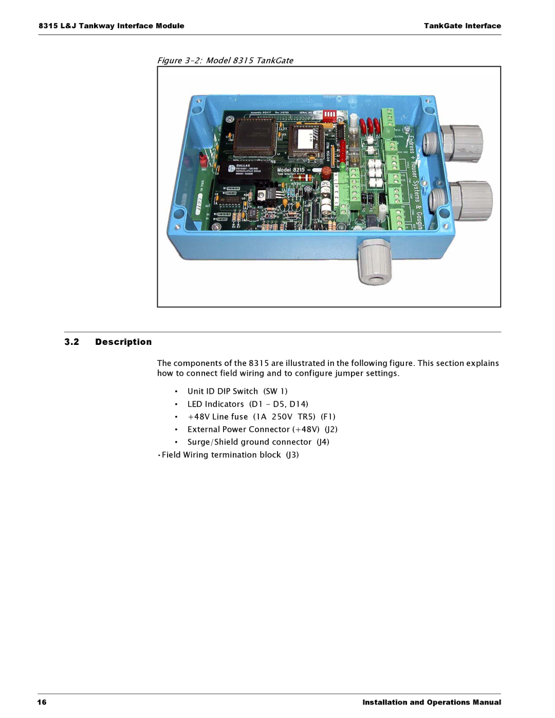
Figure 3-2: Model 8315 TankGate
3.2Description
The components of the 8315 are illustrated in the following figure. This section explains how to connect field wiring and to configure jumper settings.
•Unit ID DIP Switch (SW 1)
•LED Indicators (D1 - D5, D14)
• +48V Line fuse (1A 250V TR5) (F1)
•External Power Connector (+48V) (J2)
•Surge/Shield ground connector (J4) •Field Wiring termination block (J3)
16 | Installation and Operations Manual |