•Installation •
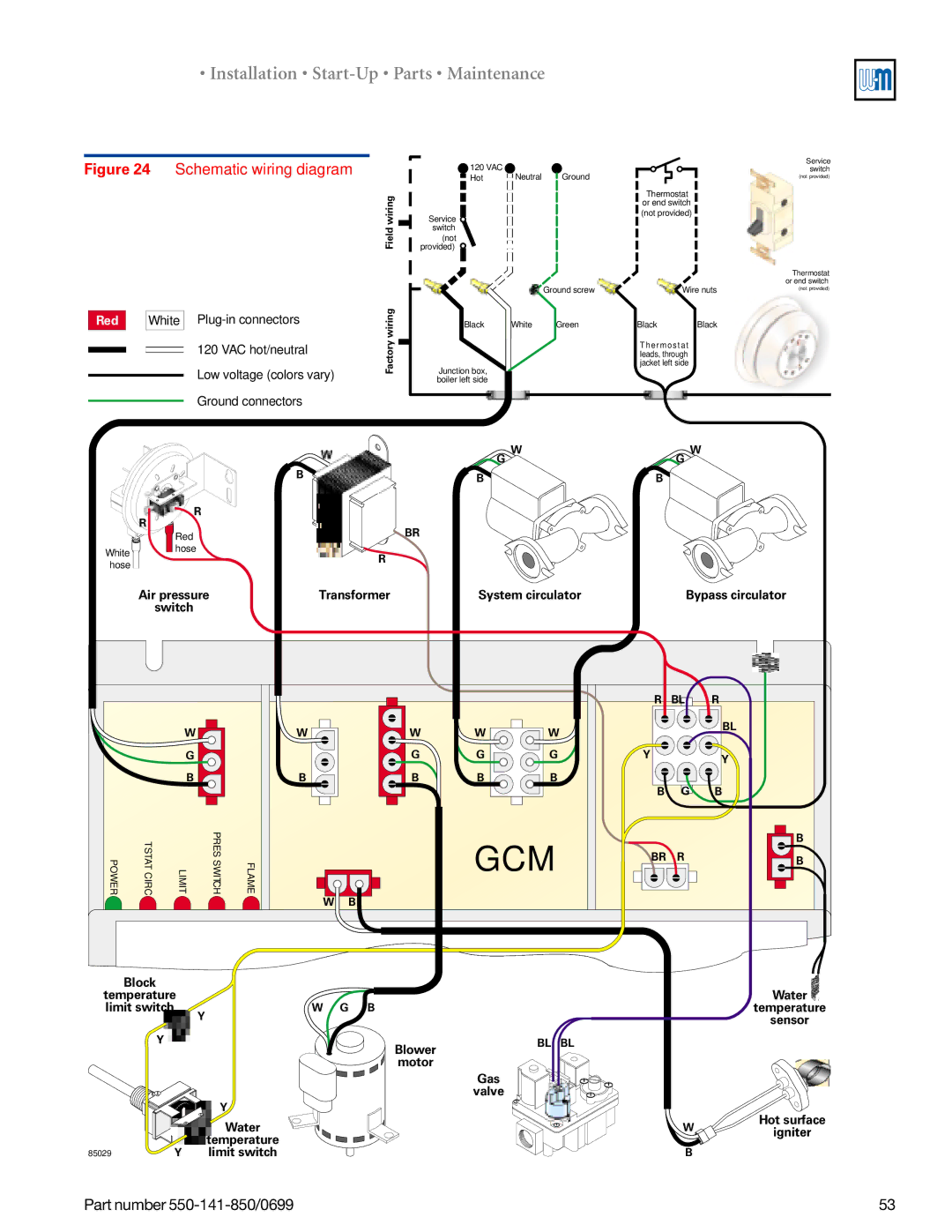
Figure 24 Schematic wiring diagram
Red |
| White |
120 VAC hot/neutral
Low voltage (colors vary)
Ground connectors
W
B
R
| R |
| Red |
White | hose |
| |
hose |
|
| 120 VAC |
|
|
|
| Service |
| Neutral | Ground |
|
| switch | |
| Hot |
|
| (not provided) | ||
wiring | Service |
|
| Thermostat |
|
|
|
| or end switch |
|
| ||
|
|
|
|
|
| |
|
|
|
| (not provided) |
|
|
Field | switch |
|
|
|
|
|
provided) |
|
|
|
|
| |
| (not |
|
|
|
|
|
|
|
|
|
|
| Thermostat |
|
|
| Ground screw | Wire nuts | or end switch | |
|
|
| (not provided) | |||
|
|
|
| |||
wiring | Black | White | Green | Black | Black |
|
Factory | Junction box, |
|
| Thermost at |
|
|
|
|
|
| leads, through |
|
|
|
|
|
| jacket left side |
|
|
| boiler left side |
|
|
|
|
|
W | W |
G | G |
B | B |
BR
R
Air pressure | Transformer | System circulator | Bypass circulator |
switch |
|
|
|
W
G
B
POWER | TSTATCIRC | LIMIT | PRESSWIT CH | FLAME |
W | W | W | W |
| G | G | G |
B | B | B | B |
GCM
W B
R | BL | R |
|
| BL |
Y |
| Y |
|
| |
B | G | B |
|
| B |
BR | R | B |
|
|
Block |
|
|
|
|
temperature |
|
|
| |
limit switch |
| W G B |
|
|
|
| Y |
|
|
Y |
| Blower | BL | BL |
|
|
|
| |
|
| motor |
|
|
|
|
| Gas |
|
|
|
| valve |
|
|
| Y |
|
|
|
| Water |
|
|
|
| temperature |
|
|
85029 | Y | limit switch |
|
|
Part number
Water ![]() temperature sensor
temperature sensor
Hot surface
W![]()
![]() igniter
igniter
B
53