button, wait for the Port LEDs to flash, and then release the SET button.
Note:
●During initialization, all port LEDs will flash ON three times.
●During initialization, all
4.RDY: (Ready) Flashes to indicate unit is operational.
5.NET: Lights when a Network Connection is present.
6.ACTIVITY LEDs: Light to indicate data activity at the corresponding port. The
2.2. Back Panel
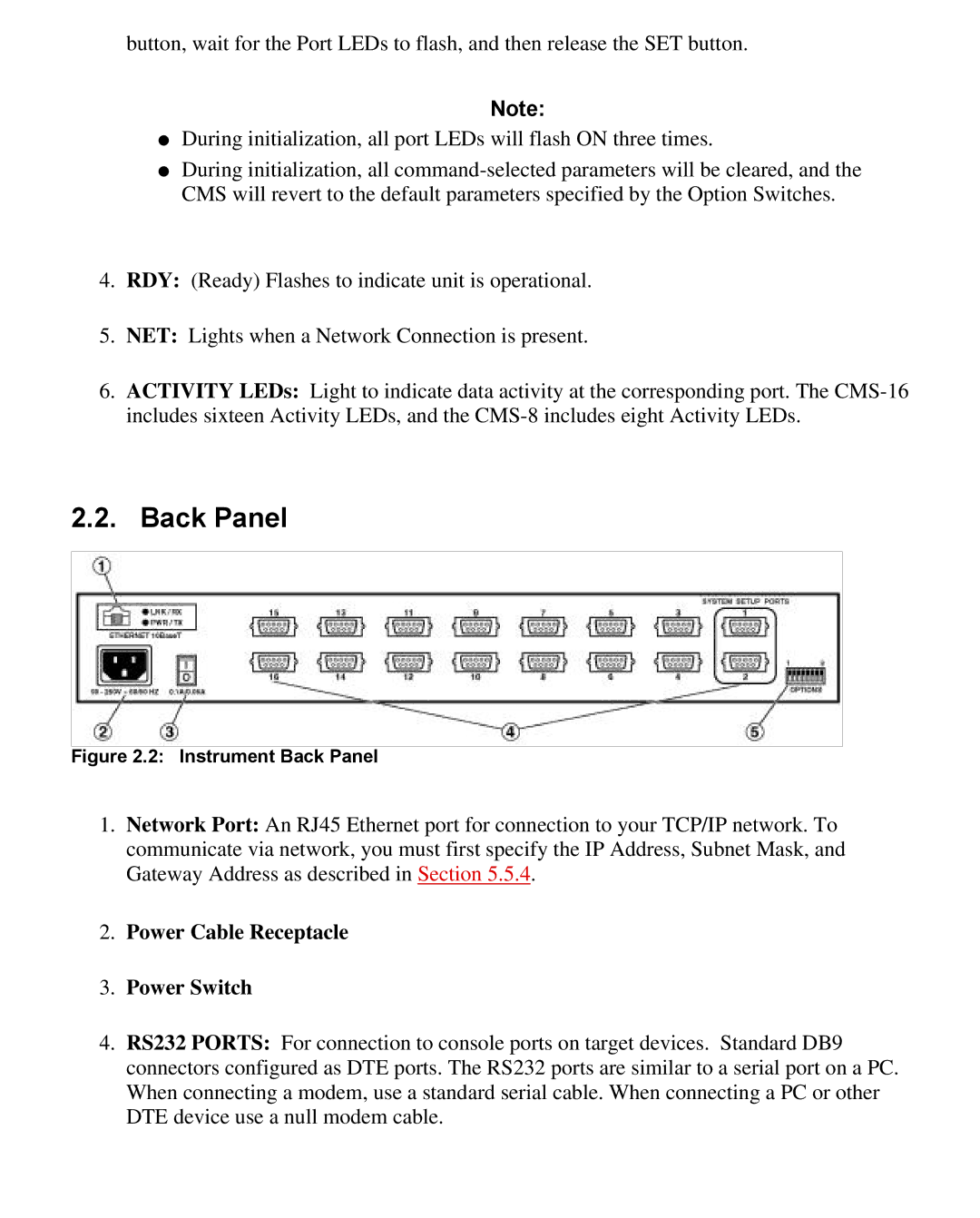
Figure 2.2: Instrument Back Panel
1.Network Port: An RJ45 Ethernet port for connection to your TCP/IP network. To communicate via network, you must first specify the IP Address, Subnet Mask, and Gateway Address as described in Section 5.5.4.
2.Power Cable Receptacle
3.Power Switch
4.RS232 PORTS: For connection to console ports on target devices. Standard DB9 connectors configured as DTE ports. The RS232 ports are similar to a serial port on a PC. When connecting a modem, use a standard serial cable. When connecting a PC or other DTE device use a null modem cable.