RF Terminal Users Guide Worth Data Inc 11/05
Page
Introduction
Table of Contents
Appendix D
Installation Sequence
Installation
Optional rechargeable batteries and a 9v power supply
Components
Connecting the Base station…
Connecting the Base Station to a serial port
How it works…
Base station channel…
Configuring the Base station…
Terminal Operation
Using the RF Terminal keypad…
To change the AA batteries
Battery Life Indicator
Finish, Sign Off Change Batteries Hit Any Key
Mm/dd/yy hhmm
Recharging the batteries
Terminal Menu Functions
Checking Batteries Please Wait………
Charging Batteries Please Wait………
Sign ON? KEY YES/NO?
Using the Windows 700 RF Terminal Loader Utility
Installing the R/F Terminal Utilities Software
Running the demo programs…
Terminal Eprom Loader Help Uninstall
Installing the Windows Terminal Loader Utility
Page
RF Terminal Setup
RF System Setup
RF Terminal Default Settings
Using the bar code RF Terminal Setup Menu
Default RF Terminal Configuration
Terminal Base Setup Voice Operations-3
Using the keypad to setup the RF Terminal
RF Setup Batteries--4 BarCodes
RS232
Group you will find the parameter
Date/Time Battery Speaker Other
RF Terminal ID
RF Terminal Setup Parameters
RF Terminal Channel
Control Keys Only
Security Code
LCD Backlight Display Mode
LCD Display Mode
Skip Opening Screens
Backlight Duration
UC31003A IDx CHn RLx 6/6 SC=N RF=NN C=N
Enter 0-9 for Volume Control Current Value is
Speaker and Headphone Volume Controls
Automatic Check Back
Key Current Value
Code 3 of 9 Code
UPC/EAN
ID character is transmitted in front of the bar code data
Code
5 Code
Codabar
MSI and Plessey
5 Length
RSS-14
Preamble
Nnmm
Postamble
Characters
Where b is the Bar Code ID character see the Code 128 setup
Scan Characters
Batteries
Beep Tone
Date Format
Set Time
Set Date
Display of Year
Voice Message Partitions
Laser Scanner Options
Shut Down Time
Aiming Dot Duration
Scan Shut Down Time
Baud Rate
Reset
Parity
Data Bits
Using the RF 700 Configuration Utility
Base and Relay Setup
@@*EdataaaaaaaaEOT
Testing the RF link between base station and host
DataaaaaaaaCR
How the Two-Way RF System works
Operational Theory
Basic RF System communications…
Here is how it works
Little more in depth…
Waiting for Host Prompt
Can I change a prompt after it has been sent?
Data Received Was Enter Data?
How the One-Way RF System works
Data Received Was aaaaaaaaaaaaaaaaaa Enter Data?
How Site Testing works
Page
Evaluating your area of planned operation
Performance Issues
Site Testing Progress, Please Wait…………
Press Enter When Ready, F1 to Exit
Nn% Good Press Enter When Ready, F1 to Exit
Performing a Site Test
How Relay Stations work…
Relay Stations
Heard by the Base Notify Supervisor Press ANY KEY
Relay n Cannot be
Determining coverage areas for Base Stations and Relays
Relay Installation
Is radio traffic contention likely?
Before you begin programming…
Hardware Failures
Failure Planning
Operator Errors
Page
LOW Level Ascii sequences directly
Programming for the RF Terminal
Planning
Host to Terminal Programming
Where
@n,m,o, data
These are valid entries for the third position character
@1,1,1,ITEM@2,1,1,QTY
Page
Line
Serial Reply
Base Station to Host Formats
2123+CR
Sign on
System Setup for details
Base Station Error Feedback
Base Shut Down Due to Host Logic Error
Addressing a Terminal not SIGNed on
Illegal Command
Sequence Error Message
?CR
@1,1,1,Scan Serial Number
Base Station Initialized Message
Automatic Check Back
Are as follows
Control Keys for Possible Programming
Setup
LOW Level Ascii Sequences using a DLL
PromptCOM/ActiveX
Test For Good Communication Serial COM
Programming Considerations for Serial COM
Multiple Base Stations
Terminal Tracking
Properties Serial COM
Concepts Serial COM
57600
300, 600, 1200, 2400, 4800, 9600, 19200
None, Even, Odd
True, False
Methods Serial COM
Ignore methods you see that are not listed here
Line, position, prompt, shifted, timestamped
Entry while scanning with the integrated laser
Line, position, prompt
Line, position, prompt, shifted
Line
Data
Count
Msgnum
Events Serial COM
Commands but software is not always perfect
Prevent most logic errors, they are still possible so
Terminal
Terminal, data
OnTermUpArrow
PromptNET TCP/IP Active X Controls
Network Setup
Programming Considerations
Server Communications
Client Utility
Test For Good Communication
Properties TCP/IP COM
Concepts TCP/IP COM
Blank or a valid file name
Methods TCP/IP COM
Basename, channel, terminal, line, position
Prompt, shifted, timestamped
Prompt, shifted
Prompt, allowbreakout, timestamped
Basename, channel, terminal
Basename, channel, terminal, data
Basename, channel, terminal, line
Basename, channel, terminal, msgnum
Basename, channel, terminal, count
Reinitialized... to indicate a single terminal re
Initialization
Events TCP/IP COM
While PromptNET/ActiveX will intercept
Commands but we may not have imagined all
PromptNET/ActiveX is designed to prevent illegal
Ways in which our customers will want to use it
OnTermRightArrow
Cameo and QL 3 Common Information
Portable Printers
Zebra Cameo Printer
Track
Zebra QL 3 Printer
Track 1&2
Part Number Description Price/Roll
Page
Tips for Using Voice Prompts
Why Use Voice Messages and Prompts?
Voice Message Operations
RF Terminal’s Voice Message Mapping
Terminal Setup-1 Base Setup------2 Voice Operations----3
Programming Voice Messages
00 ½ second message
Recording and Playback of Voice Messages
Assign Errors Cloning Master Cloning Receiver
KEY R/P?
Assigning Error Messages
Recv Setup/Voice Please Wait
Default Voice Messages
Xmit Setup/Voice Please Wait
End of Cloning Hit Any Key
Data Xmit Error Cycle Power
General Considerations
Troubleshooting
Site Test
Changing Batteries
Problems with a new installation
Message
Terminal Error Messages
Meaning Action Required
Two bases on the same channel are big trouble
Can’t communicate at all
Troubleshooting specific problems
My response time is poor
Im not getting the distance I need
Page
Get 6 beeps when the RF Terminal powers up
Problems reading Bar Codes
Reader wont beep when I try to read bar codes
Have very poor read rates when scanning bar codes
Worth Data Inc Swift St Santa Cruz, CA 95060
If you have a problem…
Opening a Base
Channel and Jumper Changes
Changing a Base to a Relay
Channel Changes
Setting the Relay ID
RS-422 Termination Jumpers
Changing the Channel on a Base/Relay
Adding Relays
Connecting a Relay Station
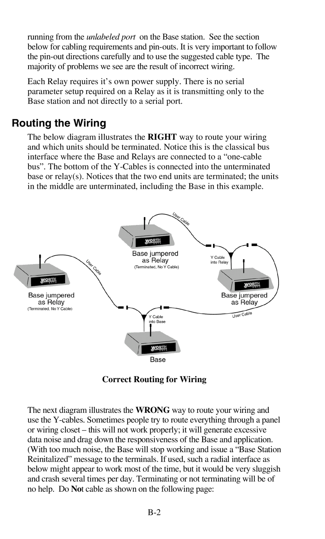
Correct Routing for Wiring
Routing the Wiring
Relay Station RS422 Pin-outs
Incorrect Routing for Wiring
Relay Test Plan and Failures
Relay Failure
Relay ID and Channel…
Testing the Relay
Changing the Channel on a Relay
Changing a Relay back to a Base
RS-422 Termination
Page
Base Station to Host Pin-outs
Serial Pin-outs
F34 DB25 Null Modem Cable
F36 DB9 Straight Cable
Relay Station RS422 Pin-outs
Laser and CCD
Zebra Cameo/QL 3 Printers
Remember
Zebra Cameo/ QL 3 to RF Terminal Pin-outs
Page
Terminal Firmware Upgrades
Firmware Upgrades
Normal Firmware Download for a Terminal
Failsafe Firmware Download for a Terminal
Base Station Firmware upgrades
C39
Code 39 Specifications
Mod 43 Check Character
Code 39 Advanced Features and Functions
+ 2 + 3 + 33 + 34 + 35 =
108/43 = 2 with a Remainder
Full Ascii Extension to Code
Start/Stop Character only
Accumulate Mode
Clear Enter
Code 93 Specifications
Page
Codabar start/stop transmission
Codabar Specifications
Page
UCC-128/ EAN-128
Code 128 Specifications
UCC-128 Shipping Container Code
Interleaved 2 of 5 Mod 10 check digit calculation
Interleaved 2 of 5 Code Specifications
Even Odd
+ 1 =
+ 48 =
+ 9 x 3 =
60 57 =
019873
UPC / EAN Specifications
Supplemental codes
Isbn Specifications
Checksum calculation for UPC-A, EAN-13 and EAN-8
UPC/EAN checksum character
130 125 =
UPC-E Checksum Calculation
183145899385
835 x 2 =
MSI/Plessey Specifications
+ 6 + 7 + 0 =
+ 4 + 14 =
4,5,6,7,2,3,4,5,6,7
943457842
+ 12 + 32 + 35 + 30 + 28 + 6 + 12 + 36 =
195/11 = 17 remainder
Laser and CCD Scanners
How to scan a bar code
Scan End Setup
Scan Start Setup Scan Laser Options
Laser Options
Aiming the Laser Dot
Difficult Code 39 Reading
Scan Start Setup Scan 2 of 5 Code
Page
Using the Scan Stand
Page
CCD Scanners
Optional Features
Laser Scanners
LI50 Linear Imager Scanner
LZ300 Laser Scanner
Laser Accessories
LZ400 Laser Scanner
PSC Long Range Laser
Page
RF Terminal Cases and Holsters
Rubber Boot for RF Terminal
F41 Leather RF Terminal Carrying Case
T46 Holster for RF Terminal
BEL
Ascii Code Equivalent Table
Aiag
Index
XON/XOFF
EDI
Logmars
ONE-WAY Setup Mode Sign on Site Testing
Speaker Volume
Waiting on Host Prompt