Owner’s
Nederland Netherlands
Read the Following Before Operating
Important Information
Copyright
Package Contents
Keep this manual for future reference
Interference
Contents
Stereo Output
Solo, Monitors & Meters
Omni Outs
Stereo Output Delay
Aux Sends
Bus Outs
Dynamics Processors 161
Effects
Scene Memories
Midi
Using the Digital Inputs & Outputs
Troubleshooting Appendix a General
Other Functions
Glossary Index
Appendix B Specifications
Appendix C Midi
Appendix D Resources 291
This chapter
Welcome to
Welcome to
01V Installation
01V Features
01V Features
01V Sonic Specs
Configuration
Key Feature Discussion
Benefits of a Digital Mixer
Four-band Parametric EQ & Library
01V Sonic Performance
Motorized Faders
Easy-to-Learn GUI Interface
Onboard Effects Processors
Onboard Dynamics Processors
Option I/O & Digital I/O
Midi
Welcome to
Getting Started
This example shows the kind of system possible with
01V System Example
Turning Off
Connecting the Power Cord
Important Wordclock Information
Turning On
Getting Started
Touring
13/14 15/16
Top Panel Controls
Analog Control Section
Parameter Wheel, Cursors & Enter
Display, Selected Channel Controls & Meters
Button Pages
Fader Mode Buttons
Delay
Function Buttons
On buttons
SEL, SOLO, on buttons & Faders
SEL buttons
Solo buttons
Return Controls
Solo Status Indicator
Solo status indicator lights up when a channel is soloed
Faders
Top Panel
Inputs & Outputs
Input BAL
2TR
Rear Panel
Phantom +48V ON-OFF Switches
Omni OUTs
Option I/O slot
Power switch
Block
Diagram
Block Diagram
Touring
Getting Around the User Interface
About the User Interface
Function Buttons Fader Mode Buttons
Display
Display
Parameter Boxes
Switches
Display Elements
Rotary Controls
Enter Button
Cursor Buttons
Parameter Wheel
DEC & +1/INC Buttons
Input Channel SEL button Examples
SEL button Fader Mode 13/14
Fader Modes
SEL Buttons
Usage Examples
Solo button Fader Mode 13/14
Solo Buttons
Master SEL Button Examples
Master on Button Examples
On button Fader Mode 13/14
On Buttons
Input Channel on button Examples
Input Channel Level Examples
Faders are used to adjust channel levels
Fader Rotary Control Fader Mode 13/14
Faders plus Return Rotary Controls
Master Level Examples
Input Channel Effects Send Examples
Title Edit Dialog Box
Getting Around the User Interface
Input Channels
Attenuating Input Channel Signals
This section provides an overview of 01V input channels
Input Channel Overview
Metering Input Channels
Phantom Powering
Pad Switches
Setting Input Channel Gain
Normal phase Reversed phase
Changing the Input Phase
Input channels 17 through 24 do not have Phase switches
For Input Channels
Attenuating Input Channel Signals
Input Channels Dynamics Processors
Applying EQ to Input Channels
Parameter Range Description
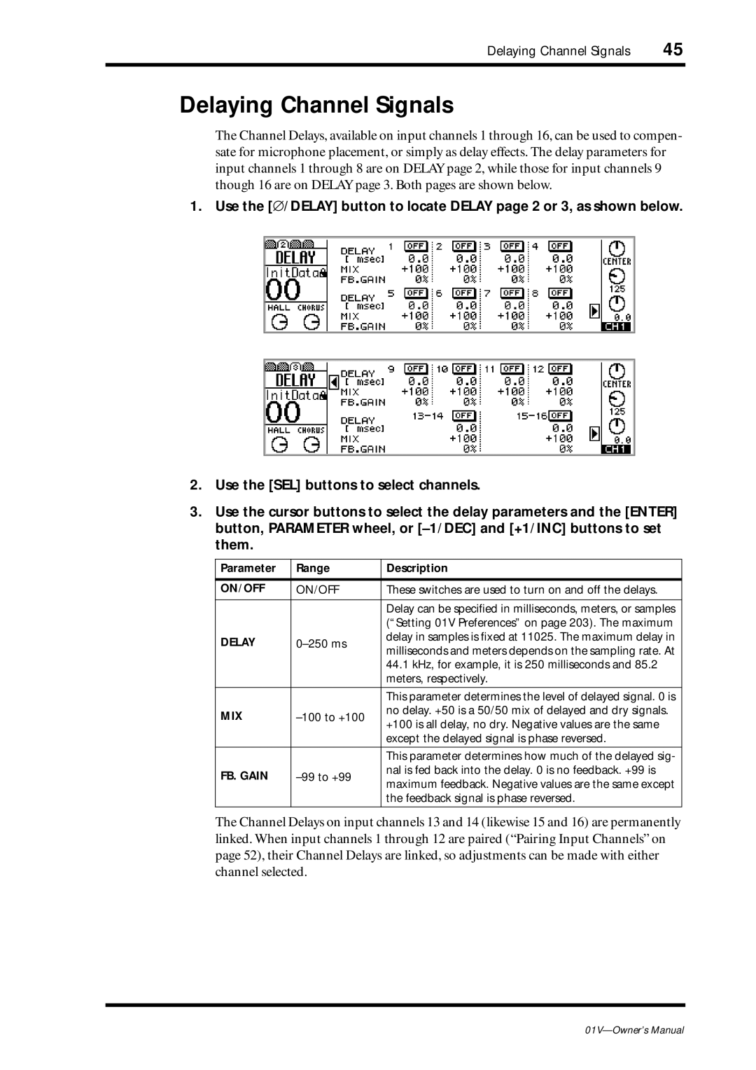
Delaying Channel Signals
Muting Input Channels
Setting Input Channel Levels
For Input Channels 1-16 & the Effects Returns
Panning Input Channels
Use the PAN control to pan the selected channel
Pan Modes
Be located using the Option I/O button
Including center, there are 33 pan positions
Routing Input Channels
Input Channels & the Option I/O Outs
Monitoring Input Channels
Input Channels & Aux Sends
Input Channels & the Omni Outs
Swapping Inputs 1-8
Making Input Channel Pairs
Pairing Input Channels
Following dialog box appears
Releasing Input Channel Pairs
Select OK, and then press the Enter button
Input Channel Pair Block Diagram
Enabling & Disabling Fader Groups
Fader group enabled Fader group disabled
Grouping Faders
Making Fader Groups
Making a Mute Group
Use the Setup button to locate Setup page 3, as shown below
Mute group enabled Mute group disabled
Grouping Mutes
Use the View button to locate View page 1 or
Viewing Input Channel Settings
Input Channels
Copying & Swapping Channel Settings
Gain
Input Channel Block Diagram
This chapter
About the 01V EQ
Adjusting the EQ
For Aux Sends
For Effects Returns 1
Press the Home button Press the Master SEL button
For the Stereo Output
ST is the selected channel
Following table contains the EQ specs
Resetting the EQ
EQ Specs
Bypassing the EQ
EQ Library
Preset EQ Program List
Title
EQ program is stored
Storing EQ Programs
Enter a title for the EQ program
See Title Edit Dialog Box on page 37 for more information
Recalling EQ Programs
New title is stored
Editing EQ Program Titles
Title Edit dialog box appears
Edit the program title
Title Parameter Description
Preset EQ Program Parameters
MID High
Corrects arpeggio tech
Use for the low range
Solo, Monitors & Meters
About Monitor & Solo
Phones
Monitor Outputs
Two-track Input 2TR
Using Monitor
Monitor Setup
To monitor, for example, the stereo out, proceed as follows
Monitor Block Diagram
Solo Setup
Use Solo buttons 1 through 16 to solo channels
Using Solo
Solo
Block Diagram
Effects Returns, Aux Sends & Bus Outs
Metering Signal Levels
Use the Home button to locate the following Home pages
Peak Hold
Main Stereo Meters
Option I/O Meters input channels
Setting the Metering Point
Use the Option I/O button to locate the Option pages
Effects Send Meters
Coaxial Digital Out & the Stereo Output
Stereo Output
Coaxial Digital Out & the Stereo Output
About the Stereo Output
Analog Stereo Output
2TR Out & the Stereo Output
Press the Home button, and then the Master SEL button
Routing Signals to the Stereo Output
Viewing Stereo Output Settings
Metering the Stereo Output
Applying EQ to the Stereo Output
Setting the Stereo Output Level
Muting the Stereo Output
Balancing the Stereo Output
300 ms
Stereo Output Delay
Stereo Output Block Diagram
104
Aux Sends
100
101
Monitoring Aux Sends
About the Aux Sends
Option I/O & the Aux Sends
Omni Outs & the Aux Sends
Use the AUX buttons to select an aux send
Sending Channel Signals to Aux Sends
For Effects Returns 1
Pre-fader/Post-fader Aux Sends
Viewing Aux Send Settings
Use the Master fader to set the aux send master level
Setting Aux Send Master Levels
Use the Master on button to turn the aux send on or off
Muting Aux Sends
Applying EQ to Aux Sends
Aux Send Dynamics Processors
Making Aux Send Pairs
Pairing Aux Sends
Releasing Aux Send Pairs
Panning Channel Aux Sends
Pairing Aux Sends
Aux Send Block Diagram
Send Block
Stereo
Aux Sends
Bus Outs
Omni Outs & the Bus Outs
Routing Signals to the Bus Outs
About the Bus Outs
Option I/O & the Bus Outs
Muting Bus Outs
Setting Bus Out Master Levels
Routing Bus Signals to the Stereo Bus
Making Bus Out Pairs
Pairing Bus Outs
Releasing Bus Out Pairs
Bus Out Block Diagram
113
Stereo Pair Bus Out Block Diagram
Bus Outs
Omni Outs
Omni Outs
Omni out signals are converted to analog
Using 18-bit D/A converters, and then output
About the Omni Outs
Omni Out Delay
Omni Out Block Diagram
Effects
About the Onboard Effects
Modulation-type Effects
Preset Effects Programs
Delays
Reverb-type Effects
Dynamic Effects
Guitar Effects
Combined Effects
Raise the channel’s fader i.e., effects send level control
Using the Effects
Faders now function as regular channels faders
Returning Processed Signals
Processed signal is returned into the mix
Press the Home button
125
Pre-fader/Post-fader Effects Sends
For Input Channels
Metering Effects Sends
Viewing Effects Send Settings
Use the Master fader to set the effects send master level
Setting Effects Send Master Levels
Use the Master on button to turn the effects send on or off
Muting Effects Sends
Muting Effects Returns
Viewing Effects Returns Settings
Metering Effects Returns
Applying EQ to Effects Returns
Monitoring Effects Returns
Setting Effects Returns Levels
Panning Effects Returns
Routing Effects Returns
Effects Library
Title the effects program
Storing Effects Programs
Effects program is stored
Recalling Effects Programs
Program is stored with its new title
Editing Effects Program Titles
EFFECT1 page 1 is shown below
Editing Effects
Setting Delay, Freq, Note & Tempo Parameters
Hall, room, stage, and plate simulations, all with gates
Effects Parameters
Reverb HALL, Reverb ROOM, Reverb STAGE, Reverb Plate
Early REF
Gate REVERB, Reverse Gate
Mono Delay
Basic repeat delay
139
Basic repeat delay with modulation
Stereo Delay
MOD.DELAY
Basic stereo delay
141
Delay LCR
Echo
Stereo delay with crossed feedback loop
Chorus
Symphonic
Phaser
Stage phaser
143
Tremolo
Autopan
HQ.PITCH Effect 2 only
Twin-voice pitch shifter
145
Dual Pitch
Rotary
MOD.FILTER
Ring MOD
Distortion
DYNA.FLANGE
147
AMP Simulate
DYNA.FILTER
Reverb and chorus effects in parallel
DYNA.PHASER
Dynamically controlled phaser
REV+CHORUS
Reverb and flanger effects in parallel
149
REV-CHORUS
REV+FLANGE
Reverb and symphonic effects in parallel
REV-FLANGE
REV+SYMPHO
Reverb and flanger effects in series
Reverb and symphonic effects in series
151
REV-SYMPHO
REV-PAN
Delay and early reflections effects in parallel
DELAY+ER
Delay and early reflections effects in series
DELAY-ER
153
Delay and reverb effects in parallel
DELAY+REV
155
DELAY-REV
Three-band parallel filter 24 dB/octave
DIST-DELAY
Distortion and delay effects in series
Multi Filter
Basic Sampler with 2.9 second memory
157
To record and playback a sample
Effects
Effects Block Diagram
Effects
Dynamics Processors
About the Dynamics Processors
Title Type
Preset Dynamics Programs
Using the Dynamics Processors
Using the Dynamics Processors
Editing the Dynamics Processors
Comp
Processor Types
Parameter Range
Gate
Announcer to be heard clearly. The same
Ducking
Expand
Compander Hard & Soft
172
Dynamics Library
Title the dynamics program
Storing Dynamics Programs
Dynamics program is stored
Dynamics programs 1 through 80 can be recalled
Recalling Dynamics Programs
Editing Dynamics Program Titles
177
Preset Dynamics Program Settings
Value Description
178
179
180
181
Dynamics Processors
Scene Memories
What’s Stored in Scene Memories?
About Scene Memories
Scene Memory
About the Edit Buffer & Indicator
Scene Memory Display Area
Mix scenes can be stored in scene memories 1 through
Storing Mix Scenes
Title the mix scene
Recalling Mix Scenes
Recalling Mix Scenes Using Midi Program Change Messages
Protecting Scene Memories
Undoing Mix Scene Recalls
Press the Enter button
Renumbering Scene Memories
Editing Scene Memory Titles
Edit the scene memory title
Setting a Fade Time
Recalling Scene Data Safely
Safe Channel switches appear highlighted for safe channels
Other Functions
Assigning Faders & On Buttons
Parameter Channel
Fader Assignments
On Button Assignments
15-16
Initial Assignments for Bank
Channel Control Parameter
13-14
198
Effect EFFECT1 PARAM1
Effect EFFECT2 PARAM1
Channel Control
201
User Assignment table
Use this table for your own assignments
Using the Oscillator
Preferences are used to customize the operation
Setting 01V Preferences
Turn off While holding down the Memory button, turn on
Initial Settings
Initializing
Calibrating the Faders
Assigning Option I/O Digital Outputs
Using the Digital Inputs & Outputs
About Wordclocks
Multitrack Recording
Digitally Recording to DAT
Multitrack Recording with Digital DAT Source
Setting the Wordclock
Using the Digital Inputs & Outputs
01V
Digital Stereo Out
Output Dither
Digital Stereo
Cascading Aux Sends
Cascading 01Vs
Midi Local Control
Link Port
Cascading Two or More 01Vs
Cascade Delay
MY8-AD 8 Analog Input
About Option I/O Cards
MY8-TD Tascam
MY4-DA Analog Output
217
Card Description Inputs Outputs Connector
Card Specifications
Installing Option I/O Cards
219
Assigning Option I/O Digital Outputs
Inputs
Option I/O
Midi
Midi Ports
Midi &
Using the Midi Ports
Using the to Host Port
01V
Use the Midi button to locate Midi page 1, as shown below
Midi Receive Indicators
Midi Setup
Using the Link Port
Mac
Setting Computer Platform Port Transmission Speed
Midi
Program Change Scene Recall
01V-A
Using Program Changes
229
Control Change Parameter Control
Using Control Changes
231
System Exclusive Parameter Control
Bulk Dump
Switch of the selected category appears highlighted
Data Type Range Description
01V
Using Midi Bulk Dump
Local Control
01V-A remote
Midi Machine Control
On Button Function MMC Command Value
Midi Machine Control
User Defined Midi Controllers
Switch of the active bank appears highlighted
01V-A
Linking 01Vs
01V-B
Linking 01Vs using the Midi Ports
System Examples
System Notes
01V & ADAT-Interface Recorder
System Components
Wordclock Configuration
Wordclock slave
Two 01V Digital Mixing Consoles Two MY8-AT Option I/O cards
Two 01Vs & two ADAT-Interface Recorders
01V-A
01V & Tascam-Interface Recorder
TDIF-1
Two 01Vs & two Tascam-Interface Recorders
Interface
01V & Pro Tools AES/EBU
01V & Pro Tools AES/EBU Pro Tools wordclock master Monitors
System Examples
Cannot access input channels
Symptom Advice
EQ F and G controls adjust
Input channel signal levels are too
254
Update some channels
Symptom Advice Added channels to a mute group
Cannot send channel signals to
Effects send meters indicate That signals are being sent to
256
Appendix a General
01V Level Diagram
Display Messages
Rack-mounting Kit
Security Cover
Appendix a General
General
Appendix B Specifications
261
Weight
Power requirements
Power consumption
Dimensions W ⋅ H ⋅ D
Input Channels
Return 1, 2 Internal Effect 1
Option I/O Inputs 17-24 need optional card
Omni Out
Bus
Aux
Stereo Out
Option I/O Output need optional card
Monitor Out Solo
Memories & Libraries
Low Lo-Mid*1 Hi-Mid1 High Gain G
Analog Outputs
Analog Inputs
Digital Audio Outputs
Digital Audio Inputs
Option I/O Cards
Control I/O
Connection Format Level Connector
01V Dimensions
Appendix B Specifications
Change#
Appendix C Midi
Scene Memory to Program Change Table
Program Initial User Change #
01V Parameter to Control Change Table
Control Parameter Change # 01V Initial Default User
275
Parameter Change # 01V Initial Default User
276
Change # 01V Initial Default User
No Assign Fader Channel
278
279
Program Change Cn
Midi Data Format
TRANSMIT/RECEIVE Data
Control Change Bn
Active Sensing Fe
Transmission Condition
Receive Condition
Parameter Change
Parameter Change bit operation for type 0x41system memory
Parameter Change 7bit operation for type 0x10edit buffer
Parameter Change bit operation for type 0x40edit buffer
Parameter Change byte operation for type 0x01system memory
Parameter Change type 0x02function calltitle
Parameter Change type 0x02function call
Parameter Value Request type 0x02function calltitle
Parameter Change type 0x04multiple linking
Parameter CHANGEtype 0x05remote meter
Request
Parameter Value REQUESTtype 0x05remote meter
REMOTEInternal Parameter Memory Bulk Dump Request Format
REMOTEInternal Parameter Memory Bulk Dump Format
REMOTEUser Define Memory Bulk Dump Request Format
REMOTEUser Define Memory Bulk Dump Format
Dynamics Library Bulk Dump Format
Control Change Assignment Table Bulk Dump Format
Program Change Assignment Table Bulk Dump Format
Midi Implementation Chart
Books
Appendix D Resources
Yamaha Web Site
Appendix D Resources
De-emphasis-SeeEmphasis
Glossary
EFF-Abbreviation for effect
Glossary
Glossary
Index
Symbols
Numerics
DIST-DELAY
Flange Freeze
HQ.PITCH
Omni OUT
Midi
Index
View page 3 59 Viewing settings aux sends
Yamaha Corporation