Seagate DL585 manual Memory options, Minimum memory requirements

Page 24

Memory options

Minimum memory requirements

Two DIMMs must be installed in bank 1 on the processor memory board in slot two.

All DIMMs on a processor memory board must have the same part number.

NOTE: Processor memory boards in slots 1, 3, and 4 can be installed without memory. Certain application programs run more efficiently if the DIMMs are balanced across all processor memory boards.

Memory population guidelines for processor memory boards with eight DIMM slots

DIMMs on different processor memory boards can be of different sizes.

DIMMs on the same processor memory board must be of the same size and have the same part number.

DIMMs must be installed on a processor memory board in pairs and in bank order.

DIMMs must populate three or fewer banks on a memory board with PC2700 DIMMs to maintain a memory clock speed of 333 MHz.

NOTE: If all four banks (eight DIMM slots) are populated with PC2700 DIMMs, the maximum memory clock speed will be 266 MHz.

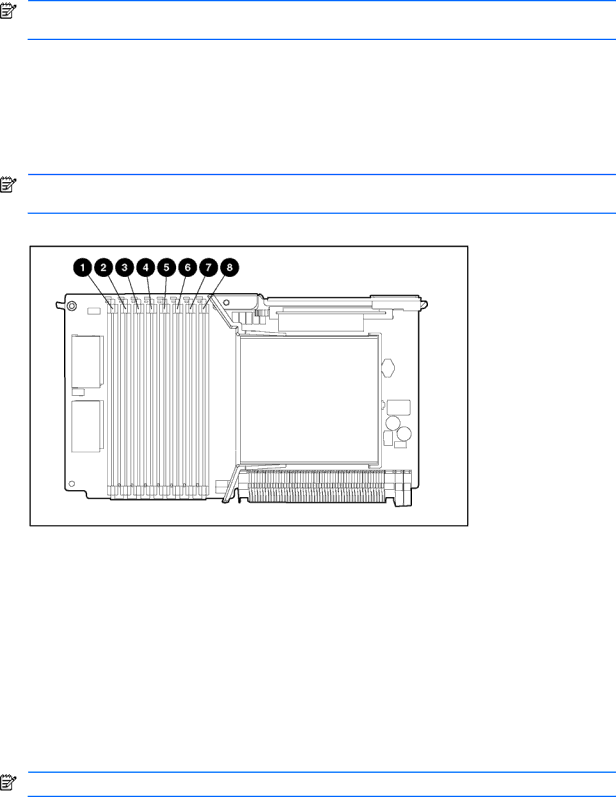
Figure 15 DIMM slots

Table 4

Processor memory board memory banks


Slot

Bank


1–2

Bank 1


3–4

Bank 2


5–6

Bank 3


7–8

Bank 4


Memory population guidelines for processor memory boards with four DIMM slots

DIMMs on different processor memory boards can be of different sizes.

DIMMs on the same processor memory board must be of the same size and have the same part number.

DIMMs must be installed on a processor memory board in pairs and in bank order.

NOTE: PC3200 DIMMs are only supported by processor memory boards with four DIMM slots.

Removal and replacement procedures 24

Image 24
Contents HP ProLiant DL585 Server Page Contents NIC Bbwce Where to go for additional help About this guideAudience assumptions Technician notesIntegrated Management Log Telephone numbersIllustrated parts catalog Customer self-repair programMechanical components spare parts list Mechanical components exploded view‡REQUIREMENT System components spare parts list System components exploded viewPPM Sdram ‡REQUIREMENT Removal and replacement procedures Safety considerationsPreparation procedures Electrostatic dischargePowering down the server Locating and removing the Torx T-15 tool Extending the server from the rackRemoval and replacement procedures Removing the access panel Installing the access panelRemoving the server from the rack Processor memory boards Processor memory board population guidelines PPM Processor Removing a processorRemoval and replacement procedures Memory options Minimum memory requirementsRemoving a Dimm Drive replacement precautions Hard drive blanksHot-plug Scsi hard drives Hot-plug SAS or Sata hard drives SAS or Sata hard drive cage Power transfer board Removal and replacement procedures Power supply blank Hot-plug power supplies Hot-plug fans Universal media drivesRemoving a drive from bay Front bezel Power button/LED assembly Expansion boards Performance balancing PCI-X expansion boardsScsi cables Front fan cage Pass-through board QuickFind diagnostic display board and lightpipe Rear fan cage Bbwc assembly Scsi backplane System battery Locating the battery on the system boardRemove the existing battery System board Removal and replacement procedures AC filter cable assembly Cutting the cable tie-wrapsRemoval and replacement procedures Removal and replacement procedures Re-entering the server serial number Diagnostic tools Diagnostic toolsPost Connectors Server component identificationRear panel Scsi backplane board connectors Scsi backplaneDimm slots Processor and PPMLEDs Front panelQuickFind diagnostic display HP ProLiant DL585 Server User Guide onHot-plug Scsi hard drives Hot-plug Scsi hard drive LEDsHot-plug Scsi hard drive LED combinations Hot-plug SAS or Sata hard drives Hot-plug SAS or Sata hard drive LED combinationsHot-plug SAS or Sata hard drive LED combinations Hot-plug power supplies Hot-plug fansNIC Bbwce Internal diagnostic display System board switches System maintenance switch SW3System ID switch SW4 System ID switch SW4 System ID Switch SW4ILO/Redundant ROM override switch SW5 Non-maskable interrupt switch Rear unit identification LED switchTroubleshooting If the server does not start Diagnostic steps Is the system power LED off?Is the internal health LED green? Servers Troubleshooting Guide Is the monitor displaying information? Error message Problems after initial boot Provided in the Factory-Installed Troubleshooting a failed processor Two-processor memory board configurationFour-processor memory board configuration Other information resources Specifications Server specificationsIndex UID LED